This thread has been locked.

If you have a related question, please click the "Ask a related question" button in the top right corner. The newly created question will be automatically linked to this question.

INA213B issue jump on outputs for certain input values

Other Parts Discussed in Thread: INA213

Hi team,

here posting following issue for INA213B on behalf of a customer :

''..We have found the following error behavior of the TI building block INA213B.

For current measurement we use the TI module Current Shunt Monitor - INA213B (Gain = 50).

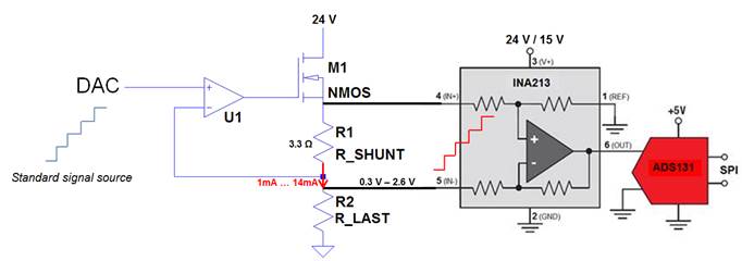
The module is used for a high-side measurement and is interconnected as in the following block diagram (see attached zip for mentioned figures)

The following diagram shows the output signal OUT on the block as a voltage value over the time. 

The voltage across the inputs IN + and IN- have been increased in equal voltage steps during time.

The green and the purple signal are each two characteristics of the output signal of two different INA213 devices in two identical independent circuits, which we measured simultaneously with the same voltage specification.

The reason why both characteristic curves do not lie on one another is due to the tolerance of the shunt resistors and the current shunt monitor.

The position of the "jump" is reproducible for a particular module, but occurs at different points in different blocks.

We have determined this behavior once with a rising ramp and once with a falling ramp, but with difference signals.

Searching for the misconduct of our circuit, we have discovered this behavior of the device.

Does this module have specific voltage ranges, which must be observed?

In datasheet I have not found any details..''

Thanks in advanec for any hints about, BR

Sergio

INA213B issue.zip

  • Hi Sergio,

    Could we have a bit more information in regards to the system? What common mode voltage and supply voltage are you using for the part?

    Carolus
  • Hi Carolus,

    here we are with some info :

    - what common mode voltage and supply voltage is the customer using for the part?

    Supply voltage: 24 V /15 V

    Input Voltage Range: 0.3 V – 2.6 V

    We have done the measurements with two different voltage supplies to check if there is a difference in behaviour.

    - it’s possible to get the full schematic/layout for the application?

    Schematic:

    - it’s possible to get a pic for the marking on top of the package to double check for production

    It is difficult to take a picture for the marking on top of the package with the camera because of the small package size (SC70) of the part.

    If it is helpful I can take a picture with the microscope.

    On the top of the package are the letters SEF.

    Thx again for kind support

    Sergio

  • Sergio,

    I've reached out to the designers on this. I'll let you know as soon as I have something

    Carolus
  • Hi Carolus,
    any news on that? Ctm is now really pushing..

    Thx again and best regards

    Sergio
  • Sergio,

    Sorry for the delay, the holiday break made logistics a little more difficult on this end. Here's what we found after discussing with design:

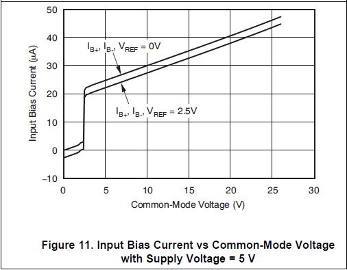
    If you examine figure 11 of the datasheet, you will see that there is an internal comparator in the part that affects input bias current when the common mode is between 0 and 5 V. Around the range of 2-2.5V, there is an instantaneous jump in the input bias current from a few microamps to almost 20uA.

    The feedback line from the DAC is driving the node on the bottom side of the shunt resistor to the voltage currently expressed by the DAC, which is more than likely pulling the common mode voltage down into this range. This means most of the 24V supply is then being drawn over the FET.

    This makes sense, as the jump the customer is seeing is 3mV. The part has an internal gain of 50, so the input voltage being added is .003/50 = 60uV. Examining the current being added to the shunt to create this, we see that 60uV/3.3 = 18.18uA, which is approximately what figure 11 shows would be added to the bias current when the jump occurs.

    Internal tolerances of the parts, and their individual hystereses could expain the random nature of where the jump is occuring in each part.

    Hope this helps.Let me know if you need anything else.

    Carolus