This thread has been locked.

If you have a related question, please click the "Ask a related question" button in the top right corner. The newly created question will be automatically linked to this question.

Issue with two XTR117 sharing same Vloop source

Other Parts Discussed in Thread: XTR117

Hi team,

This is from Taiwan sales and application team, our customer have some questions regarding design current loop using XTR117

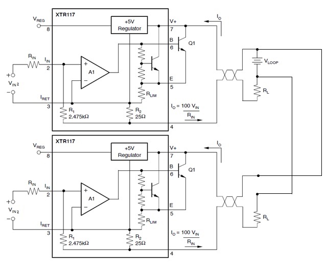
1. Our customer is using two XTR117 for two CC mode control, two current loops are sharing the same VLOOP due to there is only one voltage source available on the circuit.

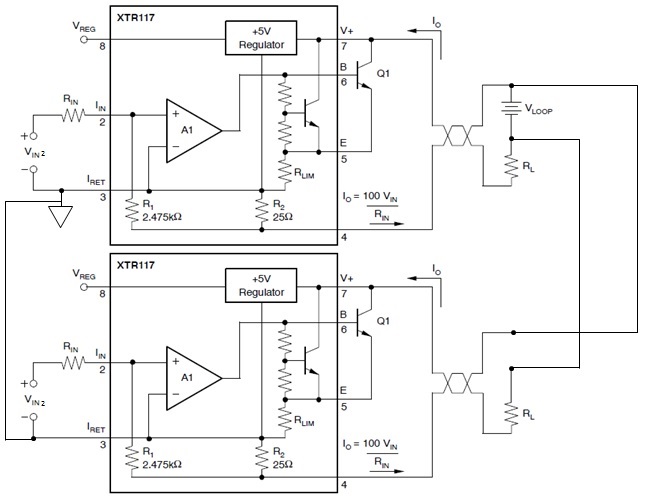
However, the output current will be dominated by the one XTR117 with higher VIN if both V- are tied to the same ground i.e. if VIN1 is higer than VIN2; IO2 will be exactly equal to IO1 with higher current level than what IO2 was meant to be.

Please see figure below:

Could you please recommend a XTR117 circuit for two separate current loops when there is only one voltage source available?


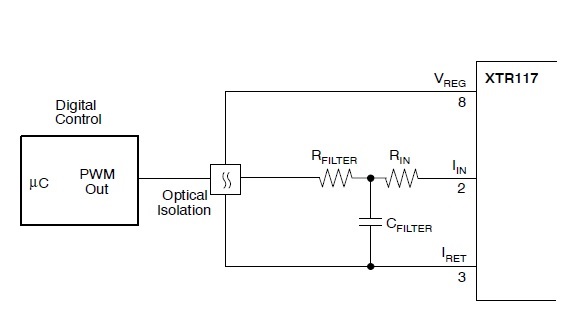
2. Our customer is passing input signal from primary side to XTR117 via opto-coupler, like figure showing below. But when VIN is zero , we can still observe around 100mV across RL (IO = 0.4mA). Is this due to the bias current of opto-couple flows to IRET pin and to IO pin via R2 to complete the current loop?


Thanks. 

Best Regards,

Wei-Hao


  • Hi Wei-Hao,

    1.)  There shouldn't be any issues with multiple XTR117 circuits sharing the same V+ supply as long as the transmitters are in parallel with each other as you've drawn them.  Please clarify what pins you're talking about when you say both V- are tied to GND?  Are you referring to IRET (pin3), IO (pin 4) or the bottom side of the two load resistors which is how you've drawn it in your image?

    2.) The XTR117 is a two-wire sensor transmitter device that is typically used to create standard 4-20mA output signals.  Because of the principles of the two-wire transmitter, the supply current for the transmitter circuitry (XTR117) is in series with the output current.  Therefore, you're current and the 0.4mA that you're seeing is a result of the quiescent current of the XTR117 and the opto-coupler.  For more information on the basics of the current flow inside a 2-wire sensor transmitter, see the following blog post:

  • Hi Colin,

    Thanks for your prompt reply. And I was referring to IRET (pin3) tied together:

    Thanks!

    Best Regards,

    Wei-Hao

  • Hi Wei-Hao,

    Tying the IRET (2-wire GND) pins of two different 2-wire transmitters will result in improper operation as you've observed.  The reason is covered in the following blog:

    The solution is to design input-isolated systems as discussed in the following blogs:

  • Hi Collin,

    Got it! Thanks for the detailed explanations on 2-wire transmitter.

    Best Regards,
    Wei-Hao