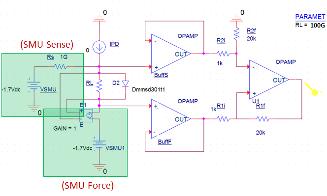
Hi, forgive me if this is a stupid question but I am not good with circuits. I am using the LMC6484AIMX op-amp as the basis of a transimpedance amplifier. I have included a picture of my circuit. It simulates correctly with the parameters shown, and I have demonstrated experimentally that it works (i.e., produces a detectable voltage at the OUT yellow marker) over a range of IPD from 2nA to 2mA. IPD is a photodiode. D2 is a Schottky diode with turn-on voltage around 0.5V.
The below circuit is only for negative voltages from the SMUs. SMU force and SMU sense boxes are models for voltage/current measurement/source units. Sense has very high impedance and force has very low.
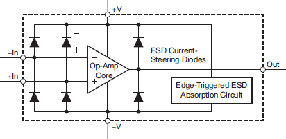
The problem is that when I try to not use the amplifier but instead measure low currents using SMU force and see what the leakage current is when I force a certain voltage. I get very high currents of 1mA when I expect the leakage current to be around 100nA from the photodiode. I suspected an extra leakage path from the 6484, so I measured a 6484 IC at various terminals (no power supplied) and found that resistances between any two pins range from 3M-ohm to 30M-ohm. This is much different from the <1pA input bias current in the spec sheet, from which I would expect G-ohm or higher input impedance instead of M-ohm. What am I doing wrong here?


