This thread has been locked.

If you have a related question, please click the "Ask a related question" button in the top right corner. The newly created question will be automatically linked to this question.

OPA454: [ OPA454 ] Start-Up Issue and Output during disable

Part Number: OPA454


[ OPA454 ] Start-Up Issue and Output during disable

Hi,

Can you help us to debug the behavior which can be seen on customer board with OPA454?
Based on the discussion below (see "Reference"), customer has changed their enable/disable circuit as below.

<Customer Circuit Schematics>:


<Issue#1: Output remains -45V for a while after start-up>:

As it can be seen from waveform below, after power-up, the output remains -45V for a while.
For this particular case, the duration is around 35sec. But some other unit shows 1sec, 45sec or even longer low period.
Since there is input signal from front opamp, it's expected to have output signal right away.


<Issue#2: Output signal during disable>:

Also from waveform below, even though the output is disabled by E/D = 0V, still can be seen the output signal which is same as the input signal.
Is this expected behavior?


<Power Up Waveform>:


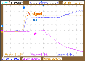
Thank you for your support in advance.
Regards,
Ken


Reference

[ OPA454 ] E/D and E/D Com Connection
e2e.ti.com/.../reply


  • Hi Ken,

    <Issue#1: Output remains -45V for a while after start-up>:

    As it can be seen from waveform below, after power-up, the output remains -45V for a while.
    For this particular case, the duration is around 35sec. But some other unit shows 1sec, 45sec or even longer low period.
    Since there is input signal from front opamp, it's expected to have output signal right away.

    I have not seen this behavior before. Most often the OPA454 is driving a lower impedance load. However, in this case, where a very high impedance load is used this unexpected behavior appears to be occuring. There may be a junction charge situation that is slowly being bled off by the high impedances. I need a couple of questions answered:

    1. If the "input" point in the circuit is connected to ground does the output move to -45 V immediately when the OPA454 is enabled?
    2. If the 200 k series output resistor is shorted does the output behave the same way?
    3. If you add a load from the output pin to ground, 4.7 k to 47 k, does the output recover faster?

    <Issue#2: Output signal during disable>:

    Also from waveform below, even though the output is disabled by E/D = 0V, still can be seen the output signal which is same as the input signal.
    Is this expected behavior?

    The OPA454 has back-to-back protection diodes across the inputs as seen in datsheet Figure 56. They can be forward biased by an input signal if there is a path for current flow such as through feedback path. Also, the diodes have junction capacitance which can couple a signal from the non-inverting input, to the inverting input/output in the buffer configuration. Adding a load to the output might reduce the amplitude of the feedthrough.

    Regards, Thomas

    PA - Linear Applications Engineering

  • Hi Thomas,

    Sorry that my reply being late...I hope you had a great year-end and new year holidays with your family.
    I have some updates from my customer, it seems that the high output impedance affects the behavior.

    ---
    1. If the "input" point in the circuit is connected to ground does the output move to -45 V immediately when the OPA454 is enabled?

    I didn't get clear information from customer, customer said "the output move to +45V...".
    But I don't think this is not valid and believe that the output move to -45V immediately.

    2. If the 200 k series output resistor is shorted does the output behave the same way?

    This 200k ohm output series resistor does not affect this behavior.
    No change can be seen even though w/ or w/o resistor.

    3. If you add a load from the output pin to ground, 4.7 k to 47 k, does the output recover faster?

    This shows the changes. The shorter Low period can be obtained with smaller resistor value.
    According to customer, with 47kohm, the low period was 100mS. Then smaller than 47khohm, the low period was even shorter.

    On the other hand, if larger resistor such as 90kohm is used, the period was being longer such as 2S.

    I ask my customer to discuss with their end-customer based on this findings.

    Thanks,
    Ken


  • Hello Ken,

    Thank you for the feedback on the customer's OPA454 circuit test results. It does appear that the output recovery behavior is due to charge storage effects in the output stage. Do let me know how the customer discussions go.

    Regards, Thomas

    PA - Linear Applications Engineering