This thread has been locked.

If you have a related question, please click the "Ask a related question" button in the top right corner. The newly created question will be automatically linked to this question.

INA282 Noise on output.

Part Number: INA282

I have implemented a current sensing circuit with the INA282 part. I have it hooked up so its output is biased to half the input rail. It's sensing on a 0.01 resistor.

The Problem:

The output is sitting at 1.7VDC as expected with a 3.3 volt input. But there is a 27kHz 1Vpp noise riding on the 1.7V output. The current monitor works as expected if I use the Mean to remove that noise. As i vary the current through the sensing resistor I see the correct change in Mean output.

Since the INA282 has a gain of 50V/V that means the 1Vpp noise should have a 20mVpp noise of the same signal on the input (if the noise is at the input at all). I put a scope on the input but do not see the noise anywhere but the output. 

The Question:

Where is this noise coming from?

Schematic

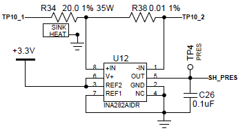
TP10_1 and TP10_2 has no connection for these measurements. The noise is present with a voltage across R38 and with no voltage.

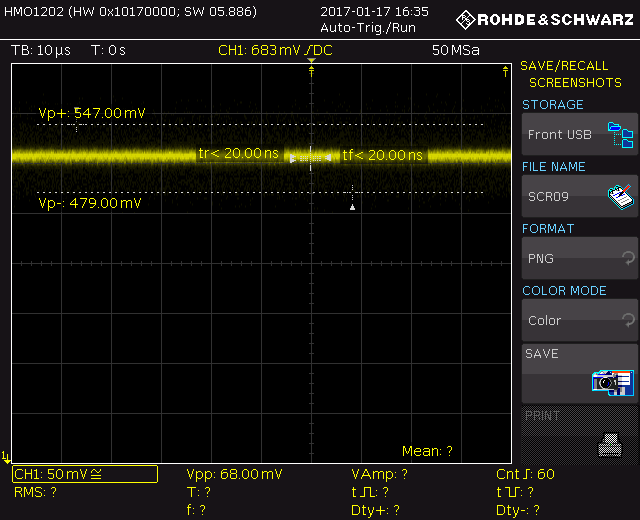
Scope of the output with respect to Pin 2 ground:

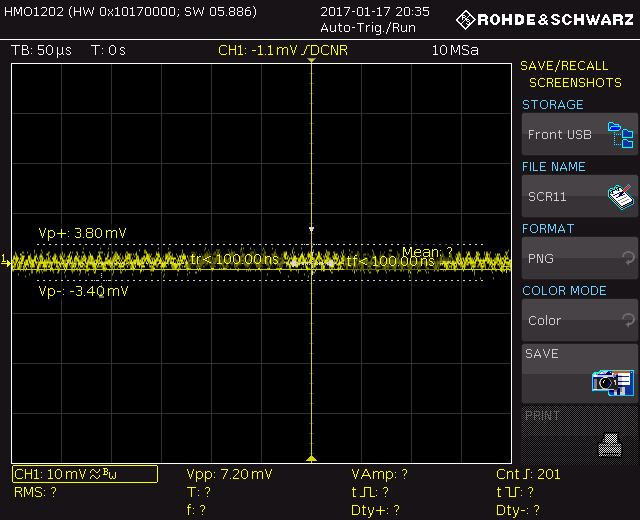
Scope of common mode input. Scope gnd probe on -IN and Probe on +IN:

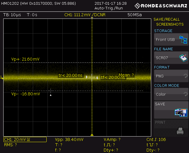
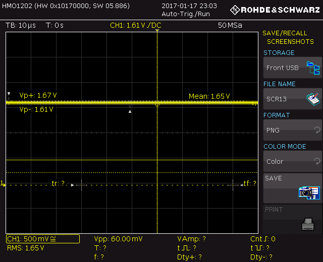
Scope on +IN with respect to Pin2 ground:

  • Couple more scope pictures.

    Scope of common mode input. Scope gnd probe on -IN and Probe on +IN (BW limit 20Mhz and AC coupling):

    Scope of common mode input. Scope gnd probe on -IN and Probe on +IN (BW limit 20Mhz and AC coupling):

    Scope of common mode input. Scope gnd probe on -IN and Probe on +IN (BW limit 20Mhz and AC coupling):

    This has a 100kHz Scope filter on it.

    It looks like there is some noise on the common mode input. But not at 15 to 20mVpp to get the 800mVpp to 1Vpp noise on the output. Defiantly not at 27kHz.

  • Dear Matt,

    The first thing I would recommend to try is removal of the output capacitor. The INA282 does not like to drive capacitive loads. If you check the datasheet, the maximum Capactivie load allowed for no sustained oscillations is 1nF.

    The .1 uF that you've attached at the output is more than likely causing these oscillations. Remove it and see if that fixes the issue. If not, could we get scope shots again of the new waveform and more detail to the input side of your system?

    Carolus

  • Thank  you for pointing that out. That fixed it.

    The output is a perfect 1.65V for half of the 3.3V rail.

    For leaning sake, why did this cause a 27kHz oscillation? I'm assuming just a stability thing with the internal feedback system? I put it there to remove any high frequency noise before entering my ADC, but now I know better.

  • Dear Matt,

    I figured that was a bypass cap. You are correct in that it plays to stability of the part. It has to do with how the capacitive load of the bypass cap reacts with the output impedance of the part. I don't know why the signal was at 27 kHz. If you want/need to filter noise at the output side, we often recommend, much like operational op amps, to isolate the output of the IC via a small resistor, and then place your cap, effectively creating a low pass filter at the ADC input. You could also place a low noise buffer in the signal chain to clean up the signal.

    Carolus