This thread has been locked.

If you have a related question, please click the "Ask a related question" button in the top right corner. The newly created question will be automatically linked to this question.

LMV7219: LMV7219 additional hysteresis

Part Number: LMV7219
Other Parts Discussed in Thread: LMH7220, LMH7322, LMH7324

Dear Mr Hooman Hashemi. Some time ago I asked a question concerning oscillation on the LMV7219 out. I send oscillograms. LMV7219 works as zero-crossing detector.

Signal from generator must be “clear” sinusoidal. But, as you can see, signal is not “clear” – there is noise on it. Why? This is measurement error of signal using oscilloscope? As you see, there is noise too on zero level.  May be, in fact, between the input +IN of the comparator and GND (0 V) there is no noise?

 Please, report, is it make sense to set additional hysteresis in LMV7219 in order to prevent switching of the comparator from noise, available on the sinusoidal signal near zero volts. I checked 6 devices and has not yet found “noise” switching of the comparator near zero volts –  you can see it on oscillogram. May be this additional hysteresis not needed?

As to R1 and R3 values, I picked them for a long time. Point is that, generator’s load must be about 10 k. This load provides R1. 

TIA

Sincerely

Vladimir Naumenkov

Picture 1: LMV7219 out

Picture 2: LMV7219 +IN

Picture 4: Generator out

Picture 5: Zero level

 2656.Circuit.docx

  • Hi Vladimir,

    This is your old post with details / schematics, for reference:

    If I understand correctly, you would like to know if the "noise" you see on these waveforms affects your zero crossing detector using LMV7219?

    You are correct that if both "ground" and LMV7219 +IN (pin 3) have the same "noise", the comparator will not be affected by it. Hysteresis will not help you either way as you're not getting output-input coupling (which hysteresis would address mostly).

    The "noise" on your "0 level" is rather periodical (about 12ns period of 83MHz). Is there something on your board operating at that frequency? If so, there may be things you can do to isolate this section of your circuit from the source of the noise. Please let me know.

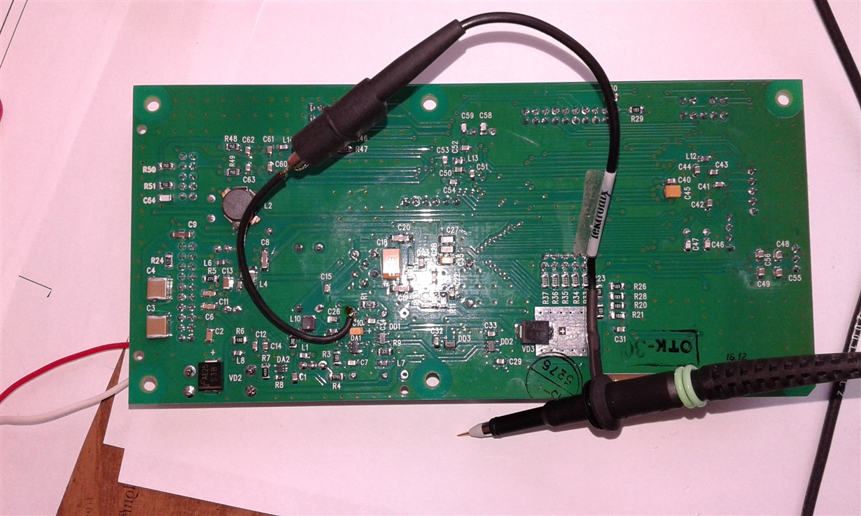
    Are you sure your scope ground lead is not "open" or otherways having a bad connection? All your waveforms look "noisy" while you should be able to get a very clean signal (at least from your source which I assume is some kind of lab / test instrument?). Most generators are 50ohm output impedance and should be terminated in a 50ohm shunt on your board. Is that the situation on your board since I don't see a 50ohm termination for your source.

    Let me know your responses.

    Regards,

    Hooman

  • HI Vladimir,
    As a test of integrity of your scope probe and ground lead, can you capture your Tek? scope's 1kHz calibration square wave (clip on the scope front panel) and share it? This is the signal the the scope puts out to calibrate your scope probe compensation capacitor and I'd like to see if it is also "noisy" or not?

    Regards,
    Hooman

  • Dear Hooman, thank you

    You understand correctly, I would like to know if the "noise" I see on these waveforms affects  zero crossing detector using LMV7219.

    To measure "noise" at the "0 level" I connected probe to GND of the generator. Possible, source of noise is external interference, but  I can not  remove them. The board will be placed in a metal case - there should be no interference.  This generator has output impedance 10 kohm. Generator requires load about 10 kohm - to ensure accurate frequency tuning. R1 and the input impedance of LMV7219 are the load of generator.  R3 is also necessary - I picked up R3 a long time, so I do not remember exactly why I put the R3, but R1 and R3 do not have to touch better - comparator works, and it is not necessary to do worse.

    I mean hysteresis 15-20 mV as output-input coupling, which is not in the scheme now.  To install resistor between +IN and OUT of the comparator? What value?

    I made oscilloscope calibration. But  I do not see too much difference. Please, see oscillograms.

    TIA

    Sincerely

    Vladimir Naumenkov

    Probe comp 2V-div

    Probe comp 100mV-div

    Zero level after SPC

    Circuit_.docx

  • Hi Vladimir,

    Hopefully putting your board inside a "can" or metal case would clean up some of your signals (if the interference you are seeing happens to be radiated and not conducted or due to localized coupling or due to grounding issues?).

    Yes, there is not anything that would prevent you from adding the hysteresis resistor you have noted from the output to the non-inverting input.

    For the values you have shown, below is the range of hysteresis you can introduce for various RF (feedback resistor) only when output is going from high to low (you cannot get any shift when going from low to high because of the way you've biased the input CM to ground):

    Vs= 3.3V

    RF (kohm) Vhysteresis (mV)
    2,000 29
    1,000 57
    900 64
    500 116

    Vhysteresis = ~ 3.3V * (R1+ Rs) / RF where Rs (source resistance) = 10kohm, R1= 7.5k

    BTW, I'd assume that you came up with the R1, and R3 values based on experimentation to set your generator load to be 10kohm, because I did not find any information the LMV7219 input impedance in the datasheet.

    Hope this helps you.

    Regards,

    Hooman

  • Dear Hooman, thank you!

    Please, answer, if the pulse duration 7-10 nanosec feed to LMV7219 input, whether it will be on the out?  (Based on the frequency characteristics of the comparator)

    Sincerely

    Vladimir Naumenkov

    www.agat.by

  • Hi Vladimir,

    You are welcome!

    You may be talking about a different application and not the 10MHz generator problem we've been talking about.

    With a 7-10 ns pulse duration on the LMV7219 input, most likely the LMV7219 output will not register a valid state (0 or 1). You may see a glitch at the output in response (although I've not bench tested this to say it will or it will not?), but it won't be a "valid" transition due to the speed of the pulse.

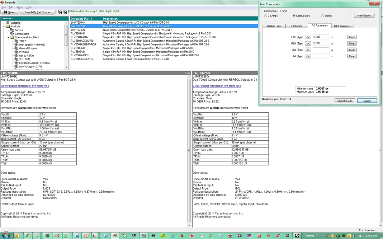
    If you need something this fast, I recommend you take a look at the list of devices shown in Selguide below (selected for < 5ns propagation delay). The fastest devices I know are the LMH7220 (2.9ns) and the LMH7322 / LMH7324 (700ps):

    Regards,

    Hooman

  • Dear Hooman, thank you
    1) I am going to use 16.3 MHz generator in my circuit instead of 10 MHz. But it will be another version of the device. The previous version (10 MHz) will be also. Will the LMV7219 work at 16.3 MHz?
    2) As to 10 MHz version, I think, as "noise" has high frequency (based on the fact that shows the oscilloscope), then it is less likely that the "noise" will be on the out (at a zero crossing point), even without additional hysteresis? All the more so after the comparator set Schmitt trigger.
    TIA
    Sincerely
    Vladimir Naumenkov
    www.agat.by

  • Hi Vladimir,

    To answer your questions:

    1. Use at 16.3MHz: At 16.3MHz, you'd be pretty close to the performance you're currently getting at 10MHz. If the propagation delay (and its skew) is acceptable in your application, then you'd be ok with using the device. I don't see any other issues.

    2. Noise, Hysteresis: Any noise on your generator should not appear on the LMV7219 output due to the action of the comparator which produces a logic (0 or 1) output state, independent of the input waveform. The noise you are seeing gets there through other means (e.g. ground bounce, interference, probing issues, etc.). Adding hysteresis to the comparator would alter the zero-crossing detection point by the hysteresis voltage you've set which may or may not be acceptable depending on your application. It would not affect the LMV7219 output waveform (in terms of noise) waveform at all! It could help you if you get false triggers or possibly output chatter due to a slow moving input.

    I hope I've answered your questions?

    Regards,

    Hooman

  • Dear Hooman!

    Thank you.

    Sincerely,

    Vladimir Naumenkov

    www.agat.by