This thread has been locked.

If you have a related question, please click the "Ask a related question" button in the top right corner. The newly created question will be automatically linked to this question.

XTR116: XTR116 - using external R1, R2

Part Number: XTR116
Other Parts Discussed in Thread: XTR115, XTR117

Hi!

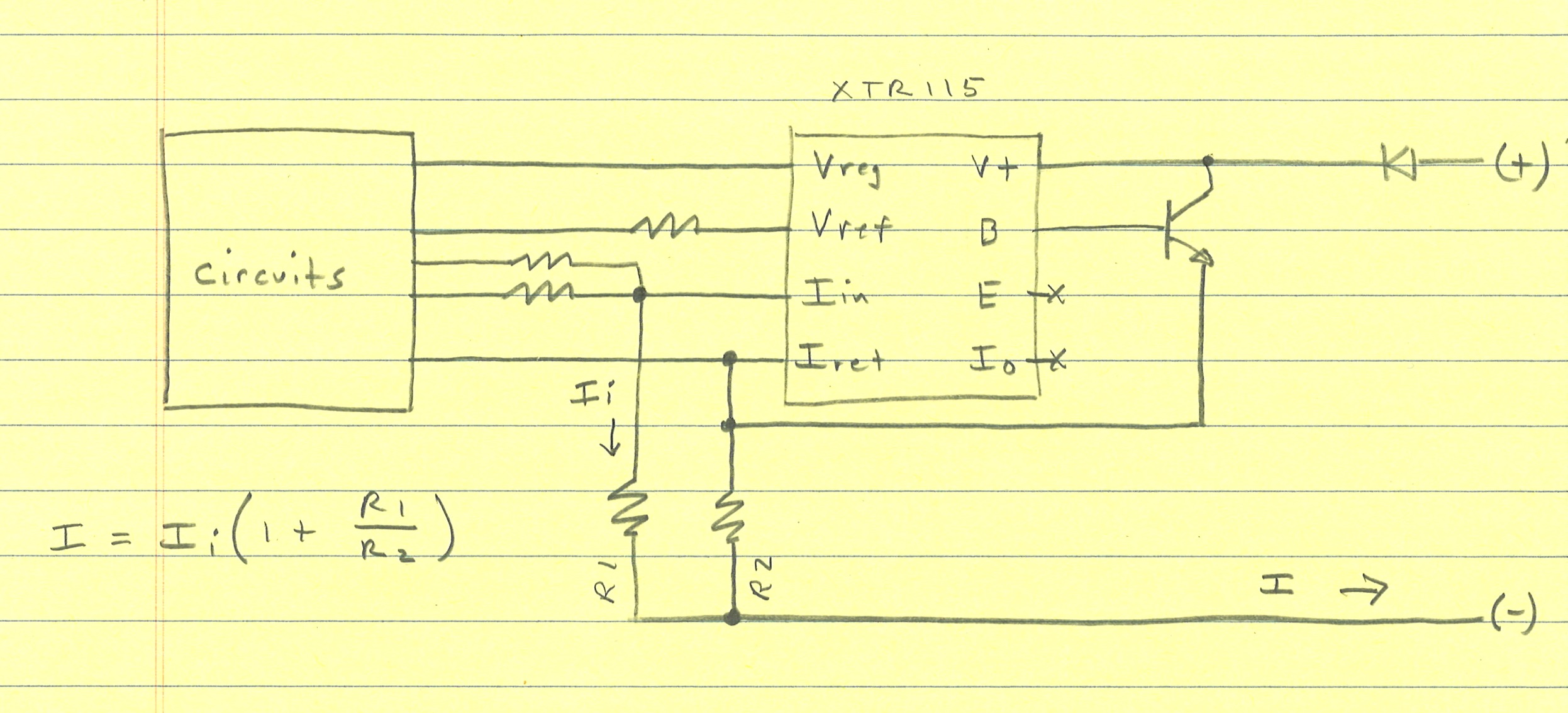
I know it's odd, but will this circuit work as intended?  

I = Ii*(1 + R1/R2)?

The external R2 (shown) will be 25.5 ohm.  R1 (shown) will be between 1k and 10k ohm (tbd).

The internal R1 + R2  = 2.5k will be across the op-amp input terminals - is this a problem?  

The internal Rlim of course will not be in effect (I may put an external current limiting resistor in series with the emitter).

Thanks!

Also, for some reason the forum changes to Precision Data Converters when XTR115 or XTR116 are selected.
  • Hi Kris,

    Thanks for the feedback, we'll look into the product sorting.

    Your suggested circuit should function as you're desiring.  We recommend including at least a 25Ohm resistor between the emitter of the BJT and the connection to R2/IRET.  This will help with current limiting and circuit stability.

    The 2.475+25 Ohms will be between the two inputs but because the inputs are only separated by the input offset voltage not much current will flow in that path. At the expense of input noise you could include a resistor in series with the IN+ pin after the external resistor connection to limit the current that flows to Vos/Rin.  See results and circuit simulation file below based on an ideal model of the XTR117.  Note that the model uses ideal op amps which can create unrealistically large voltages/currents if the circuit is connected improperly and shows roughly 0A flowing into the IN+ pin. 

    XTR117_REXT.TSC

  • Hi Collin,

    One thing, you show the external transistor emitter connected to the XTR's E-pin. 

    I want to leave both the Iout-pin and E-pin unconnected (open).

    Can you verify/simulate operation with both those pins unconnected?

    Thanks,

    Kris

  • Hi Kris,

    That connection was a mistake on my part, it's not required. No current was flowing through that line in my previous simulation so you can disconnect it and the results will be the same as shown in the post above.