Because of the Thanksgiving holiday in the U.S., TI E2E™ design support forum responses may be delayed from November 25 through December 2. Thank you for your patience.

This thread has been locked.

If you have a related question, please click the "Ask a related question" button in the top right corner. The newly created question will be automatically linked to this question.

DAC38J84: Drive DAC out with AMP and maintian high SFDR

Part Number: DAC38J84
Other Parts Discussed in Thread: LMH5401, LMH6702, THS3091

Output frequency is DC-200MHz, output voltage is 3Vpp at 50 Ohm and spur below 60dBc !

I need a high performance amp with high voltage supply,it seem to be an impossible task: the requirement HD2/HD3 < -60dBc up to 200MHz is quite high, any suggestion about AMP selection?

best regards!  

  • Hello,
    I assume you need 3Vpp at the load with 50-ohm termination. In this case the actual amplifier will have to put out around 6Vpp (or 3Vpeak)

    The op amp slew rate needed for this is 200MHz * 2*PI() * 3 = 3800V/us. To get a decent level of distortion you really need the small signal bandwidth to be at least 10x so 2GHz and the slew rate to be around 5x...this puts the slew rate needed at close to 19000V/us. We do not have any single ended amplifier that can do this, however if you are okay with a differential output the LMH5401 may be an option. For a single-ended amplifier the LMH6702 may be your best choice.
    -Samir
  • Hi,Samir

    thanks for your reply.

    A single-ended output is needed.

    I have little experience of op amp Design,what if two amp cascaded  since a single amp can not do this?

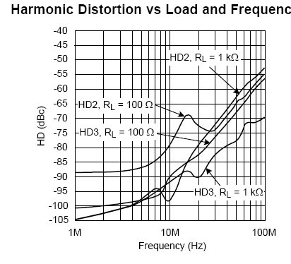
    and LMH6702 harmonic distortion performance fall below -53dBc above 100MHz,any guidance about how to improve amp harmonic distortion since requirement is below -60dBc up to 200MHz?

    looking forward to your advice

  • Hello Min,

     Cascading amplifiers in series is helpful when a single amplifier doesn't have sufficient Gain Bandwidth Product (GBP) so multiple can be cascaded in lower gains to achieve the overall system gain. For example if you need a gain of 16 and a bandwidth of say 1GHz, that would imply an amplifier with a GBP of 16GHz. If  the fastest amplifier you had was say 4 GHz, you could cascade two amplifiers in a gain of 4 each to achieve your overall gain while maintaining a BW of 1 GHz.

    In your case you are looking at slew rate which unfortunately cannot be improved by cascading. One thing that can be helpful is putting two amplifiers in parallel. Usually if an amplifier performance degrades when driving a heavy load, say 100 ohms, then you can put two, three or four amplifiers in parallel to share that load. This usually helps improve the amplifiers distortion performance, but you should see some slew rate improvement as well. You could try this on the LMH6702.

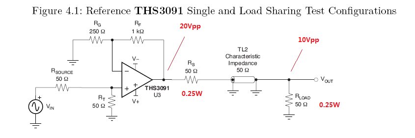
    See attached document where this was tried on the THS3091. I cannot quantify how much improvement you will get. The best thing to do is to try this out on an evaluation module.

    Evaluation modules can be purchased here

    -Samir

  • Hi,Samir

    Thanks a lot.

    putting multiple amplifiers in parallel,good idea,i am learning the app note and i have anther question to ask:the differential amp LMH5401 have much better performance than LMH6702: lower harmonic spur,high BW and high slew rate. is there a way to convert the differential output of LMH5401 to single ended,so i can get the whole energy and high ac performance( The imbalance of balun in low frequency is a problem and what's more,balun can not pass DC)?


  • Hi,Samir

    I an learning the app note and i have some question about power calculation in section 4.2,

    Q1:amp output is 20Vpp ,the 50Ohm load will see a 10Vpp sine wave ,power should be 0.25W??

    Q2:in the app note, a single THS3091 pulling 70mA from 15V rail and two parallel THS3091 100mA, Is there any way to calculate power dissipation by estimating amp's current??  

  • Min,
    Unfortunately if you want to preserve the DC content you will need another opamp to convert differential to single-ended....and that brings us back to the original problem, i.e. such an amplifier doesn't exist currently in our portfolio. :)

    -Samir
  • Min,

    10Vpp is 3.54 Vrms -> the power dissipated in the output Rload resistor is 3.54*3.54/50 = 0.25W as you mentioned.

    In the case of the amplifier:

    If the rms current drawn from the supply is 100 mA (from both amplifiers) in the shared load case, the power dissipated in the amplifier is calculated based on the 30V power supply so is V*I = 30V*100mA = 3W

    Similarly in the single channel case, if 70mA is drawn from the power supplies, then the power dissipated in the amplifier is 30V * 70mA = 2.1W.

    The math here is accurate to the 1st order.

    -Samir
  • Hi,Samir

    So,the amp output is 100 Ohm,the power dissipated in the output of amp is 0.25W*2=0.5W, the power turned to heat should be 3W-0.5W=2.5W??

    the note give a different calculation result:


    there must be something i missed,i am asking for your help and looking forward to your reply.

    best wishes!

  • Hello,
    There does seem to be a mistake in the document. So 20Vpp from the amplifier output is 7.072Vrms at the amplifier output. That then drives a 100 ohm load so 7.072^2/100 = 0.5W as you said. The resultant power in the single channel amp is this 2.1 - 0.5 = 1.6W.

    For the dual channel case it is 3 - 0.5 = 2.5W in both amps and this 1.25W in each amp.

    -Samir