This thread has been locked.

If you have a related question, please click the "Ask a related question" button in the top right corner. The newly created question will be automatically linked to this question.

OPA129: strange nonlinearity of 129U

Part Number: OPA129


Hi,

We configured the OPA129U as an inverting amplifier with G=-1.  This was achieved twice :a) RF=Ri=1M and b) Rf=Ri=10k.  The power supply voltage is +/- 12V.

When we applied DC voltage at the input and raised from zero to 0.3V, the output behaved as expected.  As the input voltagewas increased to about 3V, the about became and stayed smaller than the input voltage in absolute value (the strange nonlinearity) although it stayed negative.  The same thing happened for 10k resistors although the nonlinearity started at slightly higher voltage, it seems. The ouput was connected to a scope to check for possible oscillations but no oscillation was observed.

In addition, we observed this same effect in 2 different amplifier, one soldered on a PCB and the other on a breadboard.  The results are the same.

Any help, advice and suggestions will be appreciated.

Thank you.

  • Davorin,

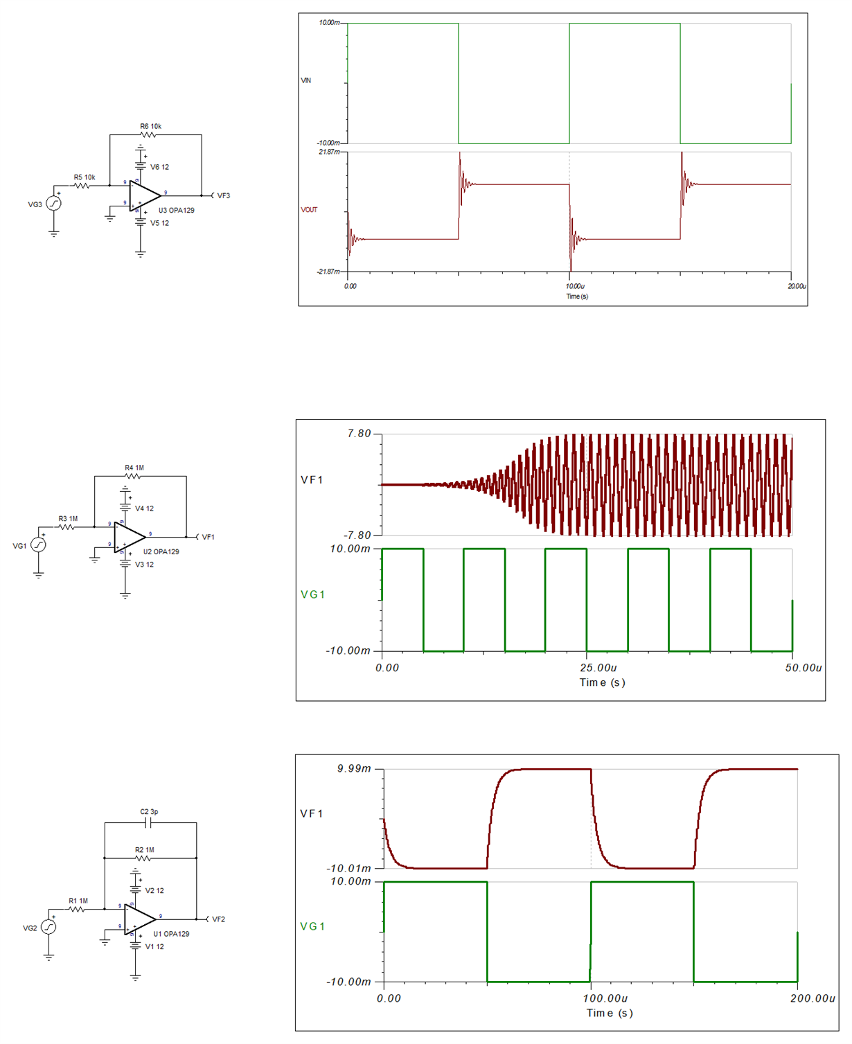
    Using large resistors for gain G=-1 will cause the actual gain to be effected by the parasitic common-mode (2pF) and differential input capacitance (1pF) and result in the zero in the close-loop transfer function: G=-Rf/(Rin||Cin) where Cin=Ccm+Cdiff.  If Rin||Cin zero occurs within the close-loop bandwidth of the part, f=1/(2*Pi*R*C), it will become marginally stable or unstable - see below.

    In order to stabilize the circuit you must either use smaller resistors to push the parasitic zero beyond the bandwidth of the part, or place a feedback cap across the Rf to cancel the zero - see below.  I have also attached the Tina schematic so you may simulate the circuit.

  • Hi Marek,

    Thank you very much for the suggestion.  We added the feedback capacitor as suggested and it made a big improvement. 

    We also noted in independent experiments that the onset of the nonlinearity seems to depend on the supply voltage value.  If we immediately applied +/-12V, the nonlinearity would be more prominent than at +/-5V bias.  Could you explain what might be happening?

    Thanks again for your help,

    Davorin

  • Davorin,

    I'm glad my suggestion fixed your problem. I am not sure what you call non-linearity; are you referring to voltmeter unexpected reading as non-linearity?  Remember that voltmeter measures only RMS value of the output signal BUT the actual signal may be oscillating.  Using +/-12V supply allows the amplitude of the output to oscillate up to 24Vpp (rail-to-rail) while on +/-5V supply the magnitude of the output signal is limited to 10Vpp.  Thus, this would explain why you see larger “non-linearity” on higher supply voltage since higher magnitude of oscillation would result in higher RMS values read by your voltmeter.

  • Hello Marek,

    Thank you for the reply.   Please let me explain what I meant by the "nonlinearity":

    The input signal for the amplifier was variable DC generated by a DC power supply and ranged from zero to about 8V.  The output was measured by a voltmeter in DC connection.  For very low input voltages the voltmeter showed the same value (with the sign changed), but as the input voltage increased, the output voltage became significantly lower than the input in absolute value.  This is the nonlinearity.

    The output was connected to a scope which showed stable signal, no sign of noise.  The fact we fixed the problem by adding a feedback capacitorr indicates that it has been a noise, definitely an AC, caused issue.  However, I still do not understand while a high frequency AC noise would affect what is a DC gain of the amplifier.  Your comments on the influence of high frequency noise on DC behavior would be much appreciated.

    Best regards,

    Davorin