Because of the Thanksgiving holiday in the U.S., TI E2E™ design support forum responses may be delayed from November 25 through December 2. Thank you for your patience.

This thread has been locked.

If you have a related question, please click the "Ask a related question" button in the top right corner. The newly created question will be automatically linked to this question.

INA283: INA283

Part Number: INA283

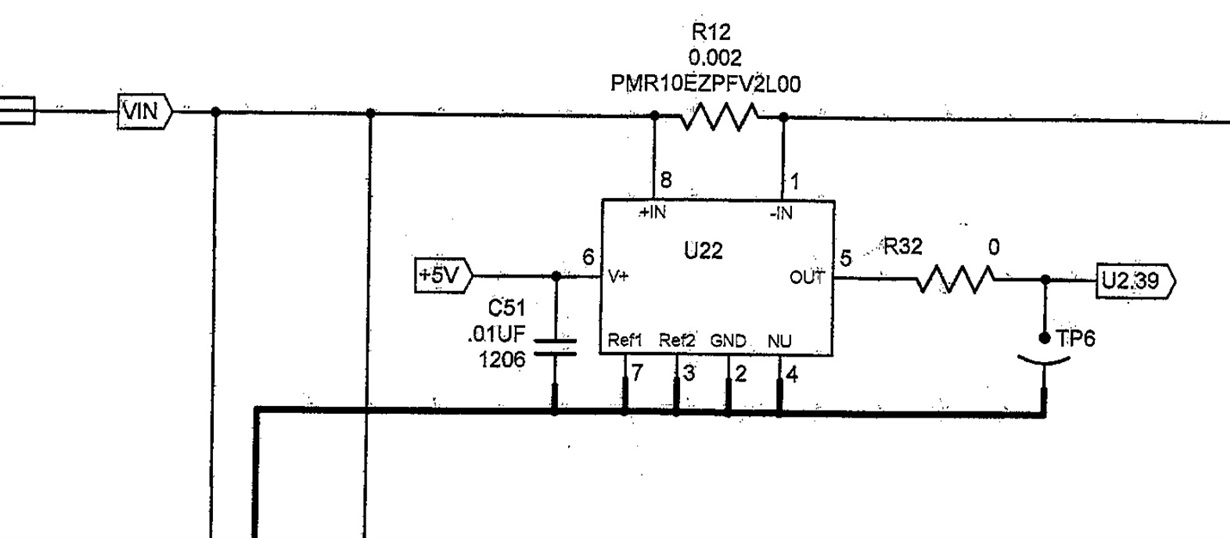
Please verify the circuit below.  I can't seem to get it to produce any kind of output voltage that I can use.

VIN range is 3.3Vdc to 40Vdc.

Pins 2,3,4, and 7 are connected to VIN return.

The current sense range is 0 to 7 amps.

U2.39 is an ADC on a Delfino processor.

Please advise. Thank you.

  • Hi Kevin,

    What you mean with "Pins 2,3,4, and 7 are connected to VIN return"? I don't see this in the schematic. I see the thick line is GND but not sure how you are connecting VIN. You are connecting GND (pin 2) to VIN? If so, this configuration will not work.
    Also, you can refer to the datasheet application section for a guideline and more information on typical connections (Page 20).
  • Hi Kevin,

    VIN return = GND, correct? Sorry I did not know that naming.

    With a current of 0 to 7A across a 2mOhm resistor you should see 0 to 14mV across the device inputs. With 7A you should be seeing around 2.8V in the output. Can you please probe the voltage in the INA inputs, differential voltage between IN+ and IN-? Also, any way you can isolate the INA or replace it with another sample to verify it is a working device?
  • Hi Mayrim,

    The  part seems to be providing the proper output voltage to sense current ratio.  The issue I am am now having is the Delifino processor resets  during a current step of 0 to 5 amps at about 500ma/uSec. I suspect it may be that I am using the same 5 volt power source for the INA283 as I am for the processor. However, there is a TPS767D301 linear regulator between the 5 volts and the Delfino. The TPS767D301 provides 3.3V and 1.9V to the Delfino. I have previously used a sense resistor in the low side and did not have the reset issues.  Will the INA283 operate with 12V at V+ instead of 5V? Is it possible the INA283 is causing a problem during the current step?

    Thanks for your input.

  • Hi Kevin,

    I am glad the INA283 is working as expected. The supply voltage range of the INA283 is 2.7V to 18V, 12V will work just fine. Did you try using different supplies already?