This thread has been locked.

If you have a related question, please click the "Ask a related question" button in the top right corner. The newly created question will be automatically linked to this question.

Amplifier gain offset configuration help

Other Parts Discussed in Thread: INA826

Hello,

I have somewhat of a general op-amp configuration question and need to get some feedback from someone more experienced in analog design than me.  I have the below schematics:

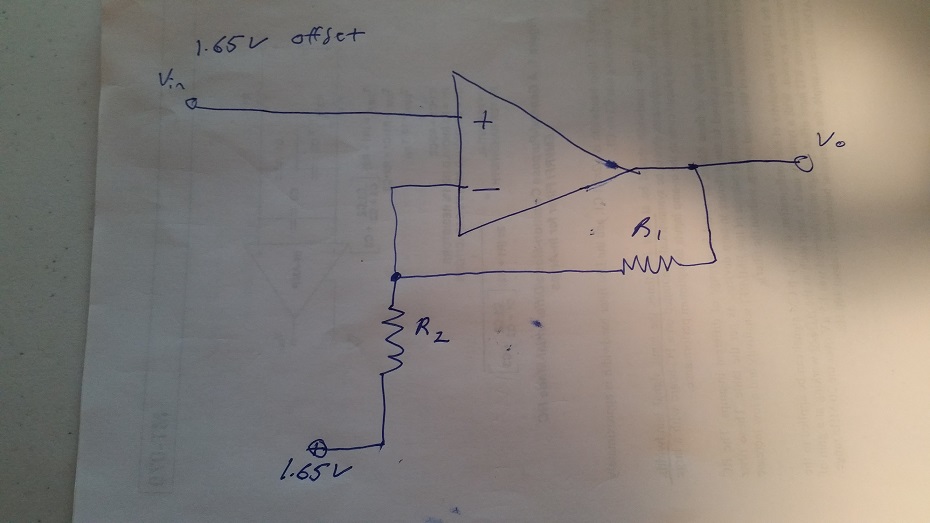
This is a single stage in an analog input channel for a product.  The input will have a constant offset of 1.65V.  This is because the sensor for this input channel is a wheatstone bridge.  If I want full DC performance my first question is, can inject an offset voltage of 1.65V to the feedback divider so I'm not gaining my steady state DC input content.  This looks like it works and I've found some app notes on the net talking about this, but I'm not the greatest analog engineer so I need some feedback. 

This would be an idea configuration for me if it does in fact allow me to gain up all the content on the input that deviates from the 1.65V stead state input.  The second part to this (assuming this is in fact a legitimate design tactic) is how do I figure out the gains?  I've calculated a transfer function, but I can't factor it in a way to get Vo/Vi like you normally would. 

So two questions:

1.  Does this make sense / is this a legit technique to accomplish applying gain to an input signal that has an offset?  I am trying to get away from AC coupling so this input can work from absolute DC to my cut Fc of the LPF. 

2.  How do you figure out what your gains are now that there is an offset in the gain feedback path?

Rob

  • Rob,

    The ideal output (ignoring errors) for your design sample is VOUT = 1.65V(bottom) + (1 + R1/R2) * (VIN - 1.65V(bottom))
    See that both the input and output are relative to the bottom 1.65V reference signal. This is not the best idea.

    That being said, a wheatstone bridge needs an instrumentation amplifier for best accuracy.
    Start here; www.ti.com/.../instrumentation-amplifiers-overview.page
  • HI Ron,

    Thanks for the reply.  This is just a small gain stage.  I actually use the ina826 in this analog channel design.   I'm trying to make this channel fully functional at DC.  This gain divideo was originally a coupled to ground.  

    Did you mean it generally isn't a good idea to interface to a wheatstone bridge with an amp like this?  If that's the case, I agree.  I am using the ina826 to do that.  The output of that will drive a low pass filter and the output of that drives this gain stage.   Or did you mean using a reference voltage in this manner in general is a bad idea?

  • Robbie,

    I now see this gain stage comes after INA826 instead from bridge directly.
    In that case, the amplifier will increase gain without increasing the 1.65V offset.
    I see no problem with the useage.
  • Awesome. I really appreciate your feedback. If I use a voltage divider and then buffer that with an amp to drive that feedback resistor divider would you recommend a particular amp in TIs portfolio for such a simple task? I assume I could just pick a really low performance one? Is there a particular family that may accel at this? I'd like to keep cost down as much as I can so I figured I'd ask...