Because of the holidays, TI E2E™ design support forum responses will be delayed from Dec. 25 through Jan. 2. Thank you for your patience.

This thread has been locked.

If you have a related question, please click the "Ask a related question" button in the top right corner. The newly created question will be automatically linked to this question.

TINA/Spice/TL084: calculation and simulation dont give me the same results

Part Number: TL084
Other Parts Discussed in Thread: TINA-TI, , LM567C

Tool/software: TINA-TI or Spice Models

Hi

I'm a total newbi in amplifiers, so please excuse me if i may ask stupid questions.

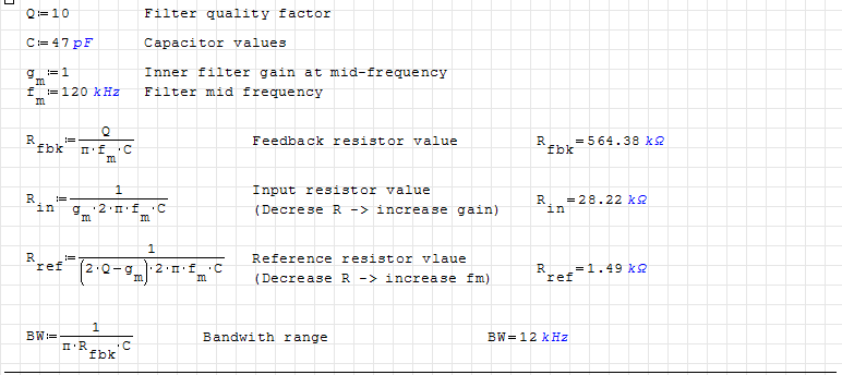
I want to realize a MFB Bandpass filter using a TL084ID.  So far so good. I calculated the resistor values according to the formulas found in  "www.analog.com/.../MT-218.pdf"

But feeding these to Tina and letting it plot the frequency response does not match with my expectations. The center frequency is far away from the 120kHz I expected.
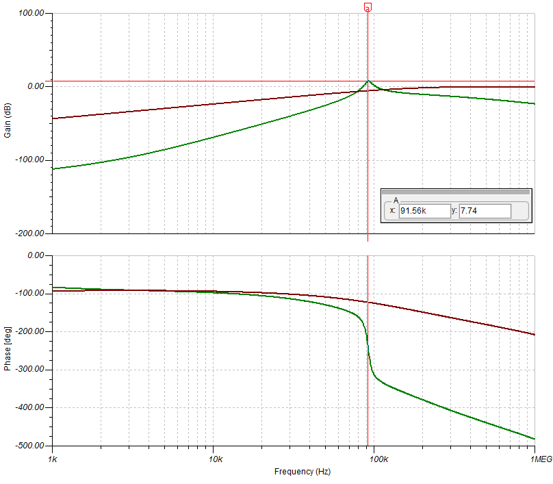
At what point did i get lost?

I also tried to use alternative calculation methods by using the (sim.okawa-denshi.jp/.../Fkeisan)  but these seem to match with my calculations. So it seems that im doing something wrong in Tina

Can anyone help?

Greets oliver

  • Oliver,

    The simple approach is to figure out how much gain the 2nd op amp is providing.
    The green line peaks about 20dB higher than the input (red line). Maybe a little less but 20dB is a nice round number.
    To get 20dB at 91k needs 910 Khz gain bandwidth.

    TL084 has a typical GBWP of 3MHz. So the 'extra gain' of TL084 is 3000Khz / 910kHz = 3.3. This is not a lot of extra gain.
    You probably never heard of a "extra gain" calculation before. Extra gain is helpful because it is used to make the input pin as a virtual zero. A virtual zero is needed for the filter to preform per design calculations. 3.3V/V extra gain will not make a good virtual zero.

    Also the R5 and R7 divider also attenuates the input signal, so more op-amp gain bandwidth is needed than I calculated above.
    The TL084 doesn't have a enough gain bandwidth for the MFB filter.

    The first stage is fine because much less gain is needed.
  • Hi Ron

    Thank you for your quick response. So if i understood you correct ... the lower the gain the higer the bandwith has to be or the other way around the higher the gain the lower the bandwith will be.

    Lets say I would want to have 40dB gain then im my case I would have a gain bandwidth of 12KHz resulting in a extra gain of factor 250 (3MHz / 12kHz) would that be enough? What value should the extra gain have.

    These assumtions are based on the following values

    R5 = 2.7k                     C = 47pF

    R6 = 560k

    R7 = 2.7k

    Maybe I have to explain my application more in detail. I have a two modulated signals on a line. one with 120kHz and one with 90kHz. My aim is to detect if the signal is present or not. Therefore i have 2 MFB bandpass filters filterung the corresponding frequency and feeding a PLL tone decoder (LM567C) that detects if the signal is present or not.

    Do you still think the TL084 can't do the job? 

    greets oliver

  • Oliver,

    The higher the gain desired the lower the bandwidth that will be available.  When desired gain * bandwidth << op-amp GBWP then circuit works per passive component simple formulas.  As gain * bandwidth ~= op-amp GBWP then thing become much more complex.

    TL084 could be used but the values will need to be tweaked to compensate for the limited bandwidth.

    If I drop a LMP8674 (55 MHz GBWP) in to the circuit then, I get a 118 KHz center.

  • Oliver,

    If you make each op-amp a single order filter and place a single order filter between each op amp stage then it will work much closer to expected results. 2nd order filters require more bandwidth to operate correctly.
  • Hi Ron

    Thanks a lot. 

    In your professional view, would you trust the TINA simulation? means...If i tweak the values in TINA to shift my frequency to the point i need it will it then be accurate with my prototyp?

    greets oliver 

  • Antonio,

    I would expect it to be close enough to simulation. I recommend doubling the capacitance and cutting resistance in half to lessen effect from input capacitance on inputs.

    I see you want to pre filter 90 kHz and 120 kHz for each LM567C. Is this really needed? I would expect the LM567C to decode properly from the same signal with 1st order low and high pass filtering. However, I don't know much about your source signal and have not personally used LM567C before.
  • Hi Ron

    your Answers help me a lot. Thanks.

    I will implement your recommendations and hope to be close enough so the design will fitt the needs. 

    The prefiltering is needed since we have a additional communication channel with a frequency of 150kHz. We have to be totally sure that the signals 90 & 120 kHz come thru properly and are not influenced by the communication.

    regards

    Oliver