Hi Team,
The customer is using INA826. He powers by +/-14V. The GAIN is set 1 and VREF is 2.5V.
Now the customer make three tests:
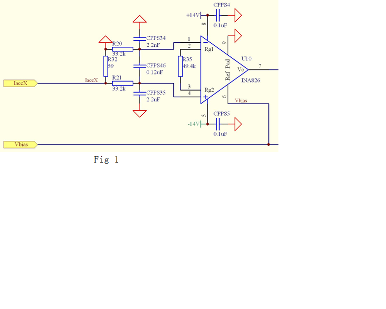
1. Please check the Fig 1 schematic. GAIN is 1. R35 is not connected. The max current of IaccX is +/-40mA. Vbias is 2.5V. There are 3 boards.
At room temperature everything is fine. When the temperature reaches 90 degrees C, the total power supply current of the system increases
from 110mA to 480mA.
The temperature of the 3 INA826 devices is higher than other areas of the board. Finally, the circuit start and stop frequently.
2. Then the customer removes the 3 INA826 devices, the total power supply current of the system remains the same from 20℃~150℃.
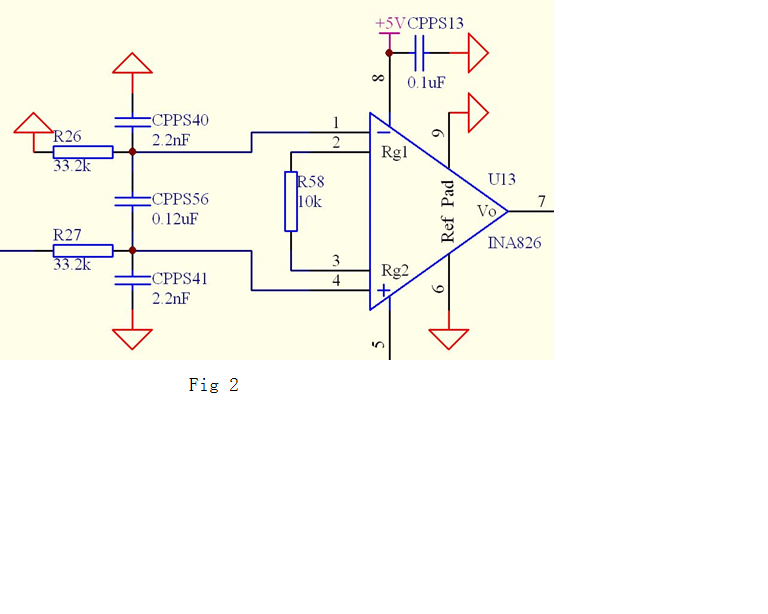
3. Please check the Fig 2 schematic. A 0.5mA current is input to the 4 pin. GAIN is 1. R58 is not connected. There are also 3 boards.
On these 3 boards, When the temperature reaches 90 degrees C, everything is fine.
I think The Fig 1 schematic. I suggest the customer he may solder the 3 INA826 devices of the Fig 2 schematic to the boards of the Fig 1 schematic.
But now he cannot do this since he needs to get the INA826 devices to the factory to weld.
Now the customer would like to replace INA826.
Q1: Can you recommend a suitable IC to replace INA826? Is there a pin to pin replacement IC ?
Q2: For the customer's issue, can you give me some solutions?
Best Wishes,
Mickey Zhang
Asia Customer Support Center
Texas Instruments