This thread has been locked.

If you have a related question, please click the "Ask a related question" button in the top right corner. The newly created question will be automatically linked to this question.

TLC271: Inquiry for TLC271CP

Part Number: TLC271

Hello team,

My customer has some questions about TLC271CP. Woudl you please advise me about the following?

Q1) What is the typical αVIO at -0C to +25C?  If you do not have this data, Tell me please.
Q2)  What 19.2uV/C and 12.1uV/C mean?
Q3)  We can get PSpice file from TI website (http://www.tij.co.jp/product/jp/TLC271/toolssoftware)
        However there are 2 files in sloj091.zip. 
        What is the defferent?

Your help would be so appreciated.

Best Regards,
Akihisa Tamazaki

  • Tamazaki-san,

    Q1) What is the typical αVIO at -0C to +25C?  If you do not have this data, Tell me please.

    We do not have specific αVIO drift information for the -0C to +25C temperature range, but it should be comparable to the typical value listed in the Electrical Characteristics table for the +25 to +125C temperature range.


    Q2)  What 19.2uV/C and 12.1uV/C mean?

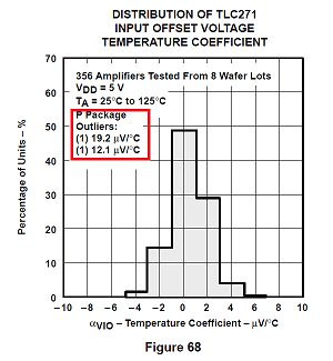
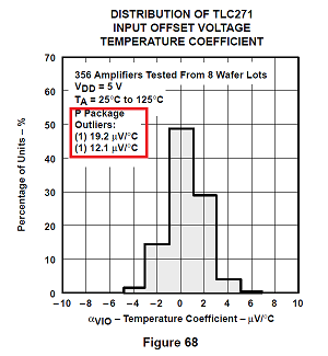
    The graph you reference is a histogram of the TLC271 input offset voltage temperature coefficient for the +25 to +125 C temperature range. Three-hundred and fifty-six amplifiers were tested and their individual drift coefficients were binned in groups 2 uV wide. The majority of the 365 devices binned in the +/- 1uV bin, and less binned in the higher drfit bins.

    One of the devices drifted with a much higher 19.2 uV/deg-C, and another with 12.1 uV/deg-C, than the majority of the devices tested. Likely, their drifts were beyond the +/-3-standard deviations (99.7 % area under curve) for the entire lot. In statistics such rare occurances are referred to as "outliers" because they fall well outside the population's distribution.

    Q3)  We can get PSpice file from TI website (http://www.tij.co.jp/product/jp/TLC271/toolssoftware)
            However there are 2 files in sloj091.zip. 
            What is the defferent?

    The tlc271readme.txt file explains what each version of the model is; Level 1, Level 2, and High, Medium and Low current bias. The Level 1/ Level 2 refers to different ways of defining the CMOS transistors used in the models. This was common in the earlier days of modeling such devices and isn't used much today. I usually use the Level 2 models, but don't usually see much difference in the simulation results from the Level 1 models. Select the model for the bias level you intend to use.

    Regards, Thomas

    Precision Amplifiers Applications Engineering

  • Thomas-san,

    I see. Thank you very much for your prompt reply.

    Best Regards,
    Akihisa Tamazaki