Because of the holidays, TI E2E™ design support forum responses will be delayed from Dec. 25 through Jan. 2. Thank you for your patience.

This thread has been locked.

If you have a related question, please click the "Ask a related question" button in the top right corner. The newly created question will be automatically linked to this question.

OPA2380: OPA380AID and OPA2380 weird amplification

Part Number: OPA2380
Other Parts Discussed in Thread: OPA380

Hi there, I m currently working on procject that needs this transimpedence amplifier. However I am having weird amplification on my setup. I am using Rigols DG1032 frequency generator and giving a sine wave with 200mV and getting out something simillar to square wave with 1.046V. I even used the OPA380 same results observed. I m not sure what i am doing wrong. Thanks for any help.

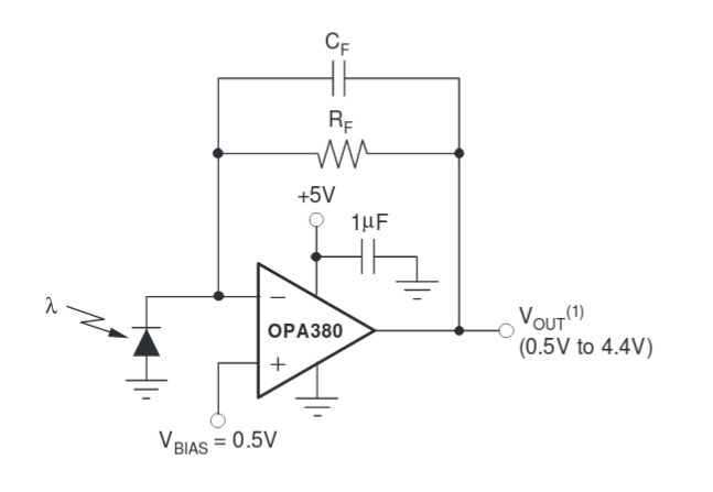
my circuit is

on this circuit i use RF=11K Ohm ressistor from pin outB to -lnB (which is input) and I didnt use any Cf parallel to this resistor( it does not do much difference) and I put V- to  and ln(B) to Ground

and 1uf capacitor from V+(supplying about 2.38V)  to ground( this also does not help with this issue)

signal values from signal generator

this my inital signal 200mV

this one signal from output of the amplifier before i turn on the power supply

and power supply settings

Amplification on osiloscope


I tried many different circuits on the manual sheet it does not give me a nice sin or triangle waves. it is good only with square wave. I also try to change power supply and input signal settings amplification changes but always have issue with the peaks

  • Hi Ilker,

    First of all, I would advise against using breadboards for evaluating high speed amplifiers with GBP > 10MHz. This is because of the stray parasitic capacitance and poor connection associated with the breadboard that could potentially make the amplifier unstable. Could you also please let us know what is the negative voltage (V-) set to? Also, a circuit diagram of the OPA380 would be helpful. Could you let us know what supply current is the part drawing?

    Best Regards,

    Rohit

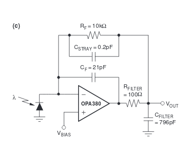
  • Thank you so much  for replying rohit. I was actually testing it with bread board and then i was going to solder it to normal circuit with low pass filter. I am using the bottom circuit as an example but i did not put Cf(it didnt help much). I just have 1uF capacitor from V+ to ground and  for V- i just ground it. and V+ draws about 10 ma which i set as limit.  I also try to give both  negative voltage and positve voltage to pin V- and V+. it trys to pull more current than 10 ma so power supply shuts down.

    .

  • Hi Ilker,

    It looks like you are operating the OPA380 at 2.38V which is below its minimum operating supply voltage of 2.7V. Also, since you are drawing 10mA of current from V+ which is set as the limit, I think I would stop testing on the bread-board as it is very likely that some connections on the bread-board are improper which makes debugging a lot more difficult as they are not solid connections. I would highly recommend to switch to the soldered circuit with low pass filter. The part should nominally draw only 7.5mA of current from the power supply.

    Best Regards,
    Rohit
  • Hi rohit, I have taken your suggestions and i am building this circuit in the manual but i have confusion that  why they put Vbias in positvie input and how much they put. usually I was grounding it. 

    and i have not tested  the circuit yet. I wonder what will be ur next suggestion if  this does not work.

    Thank you so much!

    Hi rohit, I have taken your suggestions and i am building this circuit in the manual