This thread has been locked.

If you have a related question, please click the "Ask a related question" button in the top right corner. The newly created question will be automatically linked to this question.

TINA/Spice/INA332: Differrent Output of INA332 insrtumentation amplifier

Part Number: INA332
Other Parts Discussed in Thread: TINA-TI,

Tool/software: TINA-TI or Spice Models

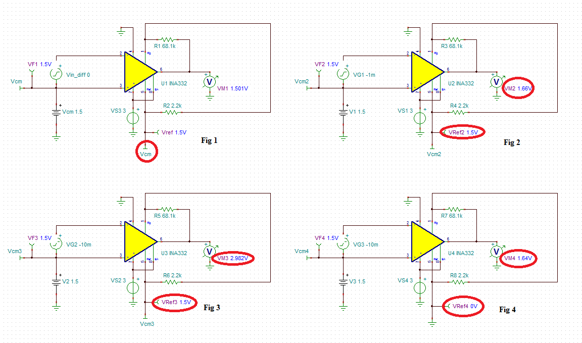
I was trying to use INA332 in my design where I want gain around 160, but I was not getting it. I have used components as given in the datasheet of INA332. 

Input voltages are 1.5V and 1.51V. and gain resistors are 68.1K and 2.2k. So, output voltage should be 1.59V, but it is giving 2.93V.

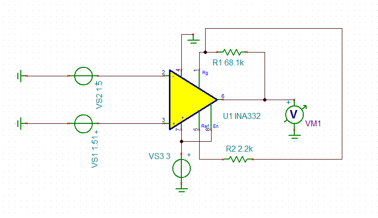
schematic is here:  1884.INA332.TSC

  • Akshay,

    It is not clear if this is a problem with the circuit configuration or the model.
    As a starting point, I will move your post to the E2E forum that is supported by the product experts for the INA332.
    If they can't resolve your problem, they can move it back to this forum and we can look at the model.

    Regards,
    John

  • Akshay,

    The issue with your INA332 circuit has to do with you floating the reference voltage, Vref.  The reference pin MUST be set to a desired voltage because the output voltage is referenced with respect to Vref - allowing Vref to float results in the output voltage saturating close to positive rail.  

    Applying Vin_diff results in the output, Vout=Vref+(Gain*Vin_diff)  

    Therefore, for Vin_diff=0 and Vref=1.5V, VM1=Vref=~1.5V – see Fig 1

    For Vin_diff=-1mV, VM2=1.5V+160*1mV=1.66V – see Fig 2

    For Vin_diff=-10mV, VM3=1.5V+160*10mV->>3.1V but it cannot get there because of 3V supply – Fig 3.  

    Lowering Vref to 0V allows the output to operate in a linear region: VM4=0V+160*10mV=~1.6V – simulation shows VM4=1.64V (see Fig 4) due to 40mV output voltage error caused by INA332 input offset voltage.

     INA332 edited.TSC

  • Thanks a lot!! That was very useful!

    But, I have another question.

    Now, I have drawn insider design of INA332, to verify results. But, there was different result.

    Schematic is here:

    Here, Vref = 1V is used as you have mentioned, output voltage is referenced with respect to Vref.

    Rf=68.1k and R1=2.2k, Vdiff.= 10mV, then output should be ~2.6V. 

    But, it is showing 1.94V.

    How is this possible?

    Detailed INA332.TSC

  • Akshay,

    Due to non-linearity of INA332 internal nodes, for Vsupply of 3V, the allowable maximum output voltage is 1.9V - see below.  

    You may download the Vcm vs Vout calculator under following link: www.ti.com/.../ina-cmv-calc

    Thus in order to be able to properly measure Vout, you will need a minimum Vsupply of 3.7V - see below.

     You may simulate this condition but in your circuit you have to use ideal op amps instead of the ones you used in your schematic- see below:

    Detailed INA332 edited.TSC

  • It is working with ideal op-amps.

    So, do you want to say that in reality i.e. while actually working with INA332 as a actual instrumentation amplifier on PCB, it will give maximum 1.9V output for configuration we have used earlier?

    Configuration: Vdiff.=10mV, Gain =160, supply= 3V.

    If yes, then is it possible at any time that INA332 will give output greater than 1.9V with other circuitry remaining the same for above configuration?

  • Akshay,
    Correct. For Vdiff=10mV, Gain =160, supply= 3V, the output voltage linear range is from 0.09V to 1.9V and the only way to increase Vout to 2.6V is to increase the power supply voltage to at least 3.7V - this is shown on the Vcm vs Vout graphs above.