This thread has been locked.

If you have a related question, please click the "Ask a related question" button in the top right corner. The newly created question will be automatically linked to this question.

WEBENCH® Tools/lmv794: lmv794

Part Number: LMV794
Other Parts Discussed in Thread: TINA-TI, , LMV793, OPA354, OPA4354, OPA2354

Tool/software: WEBENCH® Design Tools

Hi Guys,

Need to have information for this circuit and its band-pass (2 x LMV794MA / NOPB)?

1- Need +- 60db gain op-amp at 3.6V with band-pass of +- 5KHz, cF = 41KHz.
2- Need to know how to connect the 4 Vcm in the circuit, please see attached?

It will use to read an Ultrasonic sensor http://www.prowave.com.tw/english/products/ut/ep/40ep250.htm

Following link to access your design:

https://webench.ti.com/appinfo/webench/scripts/SD2.cgi?ID=194575::amplifiers::snoel@tagtracking.ca

There is the Theoretical circuit with zero piece value:

Let me know please if there any suggestion for this application!

Thanks a lot!

  • Hi Simon,

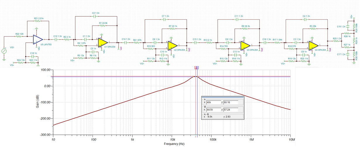
    1. To achieve a 60-dB gain op-amp at 3.6V with band pass filter of +/-5KHz and Fc = 41KHz, the circuit will be similar to the one you have shown above. I have shown below a 5-stage cascade design to achieve 60-gain band pass filtering centered at 41kHz which you can use. The supply voltage in the simulation is set to VS+ = 3.6V. The TINA-TI simulation file for the same is attached: 60dBgain_UltrasonicTransducer_5stage_LMV793+OPA354Bpf.TSC

    If you can relax the band pass filter stop-band attenuation, then it is possible to get by with lesser stages and still target 60-dB gain.

    2. The 4 Vcm connection in the circuit is similar to the one you have attached.

    Best Regards,

    Rohit

  • Hi Rohit,

    Thanks for the quick reply and all the info you give me!

    I see that you used an LMV793 for the first buffer Gain and a OPA354  for the band pass simulation circuit, is the LMV794 (only 2channel per IC) a good choice for this application?
    Or what parts would you suggest (4 channel per IC...)?

    Do you thing is ok to go with only 4 stages (50dB-60dB) for a ultrasonic sensor to a MSP430 (an) input?  

    Thanks again!

    Regards,

  • Hi Simon,

    I used the LMV793 as the first buffer gain because it has better noise performance than the OPA354 and thus, sets the overall noise floor of the signal chain. The OPA354 choice for band pass simulation is because it has higher GBW product compared to the LMV794 which helps in getting higher Q for band pass filtering. However, it is possible to use the LMV794 for this application and should be a good choice as well. You may just have to tweak the filter components a bit. The OPA354 is also available in 2 channel per IC (OPA2354) and 4 channel per IC (OPA4354).

    For an application that requires higher order filtering, I would suggest going with 2 channel per IC as it is easier to physically layout the board. Also, most of the op-amps are available in dual package which helps in swapping of parts if something goes amiss, just for flexibility.

    I think it should be ok to go with only 4 stages (50-60dB) for an ultrasonic sensor to a MSP430 input. The 4 stages are there to mainly provide 8th order band pass filtering. If you can get by with lesser filtering, then you can reduce the number of stages and increase the gain on the first stage.

    Best Regards,

    Rohit 

  • Hi Rohit,

    Again, thank you very much for all the answers, I think to go in this direction, with a LMV793 as buffer and two LMV794 for gain and filtering ...

    Let me know if anything...

    A big thank you for everything!

  • Hi again Rohit,

    I have just received the PCB with the (4) LMV794, the problem that I encounter is that there is an oscillation at 13MHz on each stage even if I remove the cap of coupling between each stages, you have an idea of who this could be the cause?

    If I set the all the stages to true pass hi gain (no filter), all is ok .

    I put the Tina-TI simulation file to the att: LMV793-4_41KHz_60dB_V4.zip.

    Let us know please...!

    Thanks again!

  • Hi Simon,

    Let me take a look at the circuit again and get back with a suggestion soon.

    Best Regards,
    Rohit
  • Hi Rohit,

    Ok Very Good,  I put an RC filter  1K Ohm and 1nF at the output and it help a lot, the little 13MHz oscillation are still there in the all stage.

    I will test over VCC voltage and temperature if is stable...

     Thanks Again...!

  • Hi Simon,

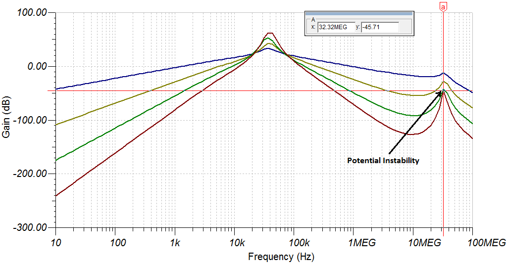
    The circuit I attached could potentially oscillate at a higher frequency using the LMV794 in TINA-TI, which cannot be noticed using the OPA354 for which the filter components were originally designed for. The primary reason for the LMV794 to oscillate is because it is a non-unity gain stable amplifier for gain of 10V/V or higher, whereas the OPA354 is a unity gain stable amplifier. The MFB band-pass filter has a noise gain shape that approaches unity at high frequency and intersects with the open-loop gain at >40dB/decade for non-unity gain stable amplifiers, resulting in oscillation. As shown in Fig 1 below, the LMV794 circuit shows oscillation at around 33MHz. The exact frequency of oscillation will vary depending upon the board parasitic and seems to be at 13MHz for your case. As I mentioned earlier, you would need to tweak the filter components in-order to get the correct response using the LMV794.

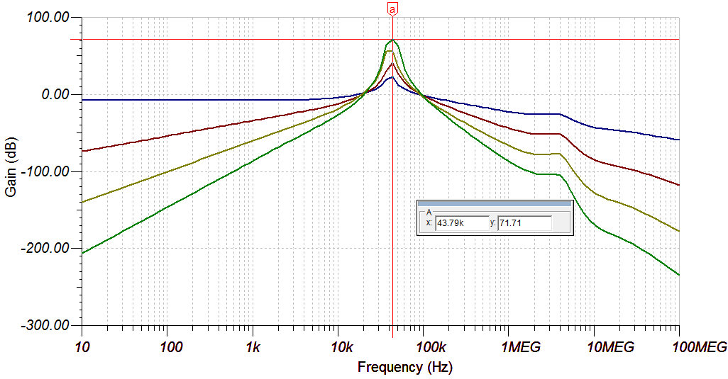
    To make the circuit stable, you would need to shape the noise gain by including a 10nF cap across the inputs of the LMV794 along-with modifying the filter components as shown in Figure 2 below. Otherwise, I would recommend to replace the LMV794 with the OPA2354 which is available in the same VSSOP package and is a drop-in replacement.

    Here is the TINA-TI circuit for the modified LMV794 MFB filter: 60dBgain_UltrasonicTransducer_4stage_LMV794Bpf.TSC

    Best Regards,

    Rohit

    Figure 1:

    Figure 2: Modified circuit using the LMV794

    Frequency response of the modified circuit: