This thread has been locked.

If you have a related question, please click the "Ask a related question" button in the top right corner. The newly created question will be automatically linked to this question.

OPA657: Acheive 0.1dB flatness on 100MHz

Part Number: OPA657
Other Parts Discussed in Thread: TINA-TI, LMH6629, OPA695, LMH6702, LMH6703

Dear Technical Support Team,


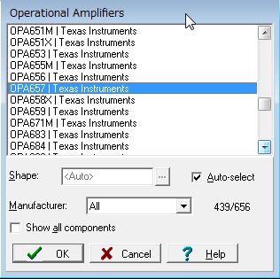
I have some questions about OPA657.

I'd like to use it for preamp of photovoltaic detector.


1.) How can I design to achieve 0.1dB flatness on 100MHz?

    When a feedbak resiter is 10kΩ, a feedback capaciter should be between 90fF and 120fF to achieve 0.1dB flatness and feedback staible on TINA-TI simulation.

    But I think that it isn't pssible to design with this small capacitor(maybe should include parasitic capacitor).

    In fact, datasheet page.21 describes below with example schematic of Figure 34 .


    Please see attached file(OPA657_TIA.TSC).

    OPA657_TIA.TSC


"This requires a total feedback capacitance of 0.2 pF. Such low capacitance values are difficult to achieve due to

 parasitics from the PCB and the surface mount components."


2.) Could you suggest more better opeamp than OPA657?


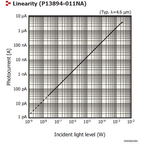
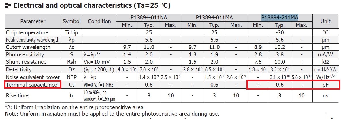
■photovoltaic detector

P13894-211MA(Hamamatsu)

http://www.hamamatsu.com/jp/en/P13894-211MA.html


■Requrement of preamp

・I/V conversion and gain from 3uA to 500mV.

・Noise: 165nV/Hz @100MHz


Best Regards,

ttd

  • Hi ttd,

    Could you let me know where you obtained the macro-model you are using in your TINA simulation for the OPA657? It appears that you were using an incomplete model that does not accurately represent the parts performance. The OPA657 does not have enough gain bandwidth to reach 100MHz of closed loop TIA bandwidth with 10k ohms of gain. Please use the link below to access your circuit with the updated model.

    OPA657_TIA_Updated_Model

    To achieve your target specs, I would suggest using the LMH6629. It has approximately 4GHz of gain bandwidth and should be able to get you close to your target specs. However, you will still likely need a low value feedback capacitor and need to design accordingly. The LMH6629 WSON package has a feedback pin located directly next to the inverting input that will help to keep parasitic values low. I would also suggest to use a 0201 components to keep parasitic capacitance down, from the feedback resistor alone you can expect about 80fF. To further control the feedback capacitor, you can add two capacitors in series to give you the ability to reduce the effective value further.

    Regards,

    Jacob

  • Hi Jacob Freet,

    Thank you for your reply.

    I used the macro-model including TINA TI.

    I guess that it has the difference between on TINA TI model and model on website.

    I think the model on website is correct.

    Our customer had been investigating LMH6629 specification.

    But unfortunately it's bias current(-35uA) is much bigger than photo diode current.

    The following figure shows poto diode current.

    Best Regards,

    ttd

  • Hi tdd,

    Your application will definitely need a FET input amplifier based on the input current sensitivity requirements. Unfortunately we do not have a part available right now with FET inputs that can support the speed requirements of your application.

    My suggestion would be to use the OPA657 in a lower gain with a second stage amplifier to provide the rest of the required gain. If your signal chain eventually interfaces with a differential input ADC, then a fully differential amplifier (FDA) can be used to convert from single-ended to differential output along with adding gain.

    Regards,

    Jacob

  • Jacob Freet ,

    Thank you for your reply.
    I'd like to consider OPA657 and a second stage apm like LMH6629 and OPA695 ,LMH6702,LMH6703.

    By the way, OPA657 spice model includes the common-mode and differential mode input capacitance (0.7 + 4.5) pF?
    Should I insert these capacitance myself?
    datasheet shows below.

    Adding the common-mode and differential mode input capacitance (0.7 + 4.5) pF and
    the trace PCB capacitance of approximately 0.3 pF to the 49-pF diode source capacitance of Figure 34,

    Best Regards,
    ttd
  • Hi ttd,

    The OPA657 model does include the input capacitance, however your 49pF diode capacitance will dominate the response. If the design has trouble reaching the required bandwidth, the best solution would be to try and use a diode with less capacitance.

    Regards,

    Jacob

  • Hi Jacob Freet ,

    Thank you for your reply.  The diode capacitance of  P13894-211MA is 0.6pF.

    Best Regards,

    ttd

  • Hi ttd,

    My apologies, I misunderstood your reference to the datasheet example capacitor instead of the one you are using. With 0.6pF I would expect you should be able to reach 100MHz with approximately 1k Ohms of gain. This will also help to increase the feedback capacitor so that you do not need such a small value.

    Regards,

    Jacob