This thread has been locked.

If you have a related question, please click the "Ask a related question" button in the top right corner. The newly created question will be automatically linked to this question.

INA214: Transient Suppression

Part Number: INA214

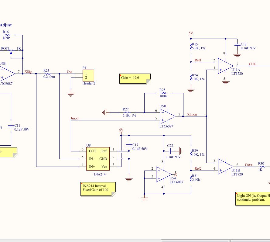
I am running a square wave (29Hz, approx 1.2Vpp centered at 2.5V) across a current sense resistor which is used in conjunction with the INA214.  Power supply to the INA214 is 5VDC.

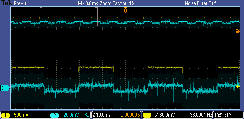
I am getting a 1V spike at the rising edge of the square wave that needs to be suppressed.   Here is a relevant portion of the circuit:

In the image below, you are looking at pin U5B-5 and you will note the transient along with some signal (elevated signature during positive clock).  

I have tried 10 ohms with capacitance tied to ground at the input pins of U8.   As capacitance increases to 1uF, transient moves from positive edge of clock to negative edge.   I also tried configuration of Figure 24 from the datasheet, but with no success eliminating the problem. I tried to lower the value of the current sense resistor to 0.1 ohm and that also had no impact to performance.

  • Hi James,

    This is cased by common mode voltage transients.
    Given the operational frequency is low I suggest increasing the value of RS and CF to implement a low pass filter. This should reduce or eliminate the spike.

    Capacitance should only be added between IN- and IN+ inputs, after RS, not to GND (with exception of VCC decoupling).
  • Increasing RS. Can Rs go above 10 ohms. If so, how high. Accuracy is not much of an issue with this design.
  • Hi James,

    Section 8.4 has a formula that can be used to calculate the induced error.
    The 10Ohm recommendation is given on the basis that the device should operate within the spec'd bandwidth with minimum error, however, at 30Hz it might require a large capacitance value for CF, if the value of RS is low, which might not be justifiable in terms of accuracy.

    I suggest starting with a few different values for CF keeping Rs = 10Ohm as a reference. If the end capacitance value required to reduce the output spikes is not acceptable, increase Rs. This way you will be able to evaluate the error and determine whenever if fits your requirements.

  • Hi Carlos:

       The following is with Rs = 220 ohms and Cf = 100uF.  No impact on leading edge spike.  As I increase Rs, desired signal disappears but spike remains.    Why would this not show up on simulation model? 

  • My bad. I noticed the solder to the lead on the large 100uF had broken. No pulse but no signal as well. However, tried this with 1uF and pulse was still present. I will try 10uF. Would increasing the value of the current sense resistor help, or would the pulse appear again with the signal present?
  • Hi James,

    I will run this setup on our lab and I will follow up with you shortly.

    As far as I understand the requirement is to detect a 30Hz square wave and its amplitude, am I correct?

  • Hi James,

    I run the setup as per your schematic on the lab and didn't found any significant overshoot for an input voltage of 10-100mV. Naturally at 100mV input the output saturates to the VCC Rail. No filtering was employed.

    The figure below shows the output of the INA214, blue trace = Input (11mV), Yellow trace = Output (1.1V). The noise on the low trace is an artifact from the oscilloscope.