This thread has been locked.

If you have a related question, please click the "Ask a related question" button in the top right corner. The newly created question will be automatically linked to this question.

Electrical Conductivity circuit design

Other Parts Discussed in Thread: TLV341

Hi All

I have been advised by Victor to make a posting on this forum.

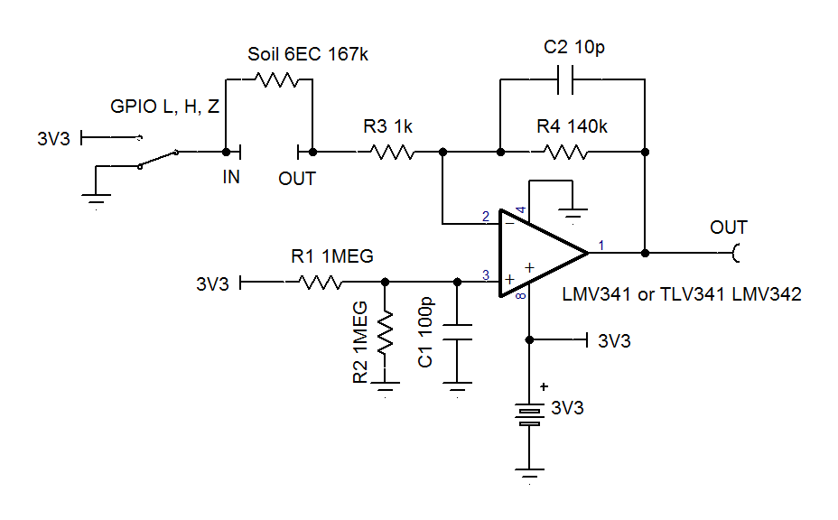
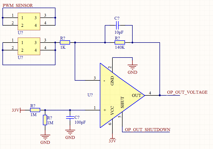
I need to develop a EC circuit that can work conductive probes to measure EC levels in various types of substrates and water.

From my understanding i need to use some form of amp circuit.

And the signal outputted to probes needs to be AC signal.

The AC signal will be a Sine Wave, which i can use the PWM from my micro controller with a possible filter. 

As its a AC signal , if i am correct voltage needs to + and -, could i get a circuit running with +-3.3V, so i can power it using batteries? 

But when it comes to the amp design i would need some advice on best way to achieve this? 

I been also been advised to keep probes 1cm apart.

Does the applied voltage on probes have an effect or correlation to EC levels, for example if 3.3V was applied compared to 12V? What i am asking even though voltage is low, can i have full range of EC represented  propositional on my circuit? For example from 0 to 6 EC from 3.3V.

I await for your reply

Thank YOu

  • Dharmesh,

    Google provides a good answer for this.
    "The resistance of the solution (R) can be calculated using Ohm's law (V = R x I). Conductance (G) is defined as the reciprocal of the electrical resistance (R) of a solution between two electrodes. The conductivity meter in fact measures the conductance, and displays the reading converted into conductivity."

    If the voltage on the electrodes is increased or decreased then the current flow will change in the same ratio (if the conductance remains the same).
    What is the expect current range to be measured.?
  • Ron

    Thank You for your reply

    In regards to current range, as i am measure soil and water based solutions i aim to keep current low as possible to save battery power.

    From what i understood an amp is required is there a reason for this?, but what happens if i was to generate sine wave and output it to electrode, then when i receive the signal convert it back to DC to work out the EC levels.

    My aim is to make a meter that can produce a EC reading up to 5EC.
  • Dharmesh,

    After some reading I see that 1 EC = 1 uS or 1 microamp per volt. So 6EC would be 6 uA/V or 167k ohms.

    Here is a circuit that can read 6EC plus some margin.

    Let H = 1/2 of a single +3.3V supply. No dual supply is needed.

    VOUT = H +/- H * EC * R4 / 1e6 or in this case 1.65V +/- 1.65V * EC * 0.14

    The op amp should have a shutdown pin to save power when not measuring. The GPIO (general purpose in/out) would be high Z

    When measuring set GPIO high then measure VOUT then set GPIO low for the same amount of time and measure again.

    This will meet the requirement for AC (square wave) input signal. The 1k resistor is to help with ESD protection.

  • Dear Ron

    Thank You for your reply

    Got few questions so I further understand the design.

    1. You mentioned the H needs to be 1.65V, do we need to setup the power supply do the 3.3V LDO becomes +-1.65V?

    2. Shutdown pin is not a problem, if the IC does not have it I can always add a load switch.

    3. If I am correct the op amp will output a voltage, therefore I need to setup a ADC on my uC.

    4. You mentioned “When measuring set GPIO high then measure VOUT then set GPIO low for the same amount of time and measure again.” , what is the reason for this?

    5. In regards to my AC signal, I am thinking out using a PWM signal and let it go via low pass filter . From my understand the probes must have AC signal , would this need to be +-1.65V?

    In addition to this there should also be temperature sensor as EC is effected by temperature as well.
  • Dharmesh,

    A1) R1 and R2 make the 1.65V automatically.
    A2) Yes, that is a good solution.
    A3) Yes ADC is needed.
    A4) If a DC voltage is used then one probe would corrode much faster than the other probe. Using the same time for each probe voltage polarity will make probe wear slower and even.
    A5) The "input" probe self biases to 1.65V (1/2 VCC) the output probe should vary from 0V to 3.3V (zero to VCC). You could make a sine wave, but I do not think that is necessary.
    A6) As I read yesterday (meaning I am no expert for soil properties) temperature correction is needed. So Yes.
  • Dear Ron

    Thank for all your help.

    Just want to clarify few things before making a proto pcb.

    1) You mentioned the input and output probe.

    “The "input" probe self-biases to 1.65V (1/2 VCC) the output probe should vary from 0V to 3.3V (zero to VCC). You could make a sine wave, but I do not think that is necessary. “

    According to the schematic posted ,isn’t the GPIO pin connected to the input probe, which will vary from 0 to 3.3V and output pin is connect to the AMP that will self-bias.

    2) In regards to probes corroding, from what I have understood this could be avoided using an AC signal instead of DC. If we could create an AC signal and use a simple diode circuit to achieve AC-DC?

    3) Is the 167K an actual resistor between the probes or shown in schematic of soil representation?
  • 1) I had 'in' and 'out' swapped in my text.
    2) You can do that.
    3) soil representation
  • Dear Ron

    Thanks

    I think i will start with my proto PCB design, i feel for my probes i could use conductive metal like staineless steel probes for long life.

    In regards to having a AC signal that is also negative, i presume my amp must also have a negative power input?

    At this stage i will experiment with all the variation for the best solution., but hoping good steel probes with a square wave will prove to be good.

    thanks
  • Dharmesh,

    The voltage across the probe will be AC. It is AC voltage with peaks of +1/2 VCC and -1/2 VCC.
    The circuit ground does not connect directly to earth ground nor the probes. Therefore the probes will be AC voltage relative to each other and single polarity voltage relative to system ground.
  • Thanks

    Will be getting the PCB made this week.

    I am think about imputing a square wave that is about 20 Khz, would that be ideally?

    And the voltage output of the amp, would i be correct in saying it will be a max 3.3V?

    Thanks

  • Dharmesh,

    I have no preference for frequency and no knowledge of effect of probe lifetime.
    At some very low frequency probe life may be impacted. At very high frequency op-amp won't be able to follow signal.

    Amp output will not exceed supply voltage for op amp.
  • Thanks

    I am thinking about between 5Khz to 40 Khz, would that be to to high or low?

  • Dharmesh,

    40kHz is 25us cycle time which is 12.5us per square wave clock edge. If output needs to change 3V for high conductivity soil then output can take 3us to get to new level plus a little time to settle. Therefore this should work.
    5kHz is not too slow in my opinion as current flows one way for only 0.2ms before switching the other way.
  • Thanks,

    Sorry,  my frequency will be actually 43.369Khz.

    Will have the PCB made this week.

    Thanks

  • Dear Ron

    Got my test board, but before i actually start placing it with substance, i want to test the concept with various resistance to confirm that circuit is working.

    Currently i am input a 42 Khz square wave into the circuit and output is just about 1.65V.

    When i tried with frequency of about 276 KHZ, i got an output of 3.3V and would gradually decrease as resistance increased for example 50K,

    Should it be preforming in such manner and now my frequency is much higher then 42Khz?

    Would i also be correct in saying that voltage output will vary from 1.65V to 3.3V?

  • Dharmesh,

    The input clock is an AC signal and the op-amp output will also be a AC signal.
    At 42 kHz, I expect the op amp DC (average) output will be 1.65V with or without a earth substitute resistor.
    At 276 kHz, the op amp wont; be able to follow the input signal and the output will be distorted.
    Use an oscilloscope to measure the output.
  • Hi Ron

    Thank for your reply.

    What i was expecting, was to get a variation in voltage as my EC or resistance between probes was to change.

    Yes i am seeing a nice clean 43.201 Khz output , when input is the same. 

    So as EC changes should i see a variation in frequency or voltage, and how can i try to simulate the concept before applying in field testing?

    I am using TLV341, which i believe works far as 2.3 Mhz?

  • Hi Ron

    For your reference, please find attached my circuit.

    My uC is outputting PWM 43.2Khz on one of the terminal labelled "PWM_SENSOR"  

  • Hi Ron 

    Sorry for the questions.

    If the output of the Op-amp is AC, then i need to make it a DC. I have used a simple diode circuit that will convert that to a DC signal, 

    With the diode i am seeing a slight change in voltage output: for example

    No Ristance = 1.5V

    1M(1EC) = 1.63V

    2M(0.5 EC) =1.53V

    3M (0.333EC)= 1.50V

    Does this seem right?

    I was expecting voltage to range from 0 to 3.3V , as EC increase from 0 to 5EC.

    Regards

    DJ

  • Dharmesh,

    The simple diode benefits from a storage capacitor and a draining resistance.
    0 EC will be 1.65 minus diode drop, so I'd expect less than 1.5V
    1 EC is higher than 0EC so that is the right direction.
    I would expect a range from roughly 1.1V to 2.75V

    What is the sample time and conversion time of your analog to digital convertor?
    I originally thought you would read the AC low and high level sample with the ADC.
  • Dear Ron

    Thank You for reply

    I have manged to get it working, sorry for the previous messages.

    It seemed that using a standard voltmeter was not a good idea, by using a scope and a delay to my  ADC  got it working.

    I am now taking sample at the midway point on both positive and negative pulse wave. This way the difference between them gives me the voltage.

    I have learnt that as EC increases from 0 to 6EC , it is not necessarily linear, and therefore will need to do practical sampling then repeat against various temperatures to get my final results accurate. 

    I have now reduced my CLK into the opamp to 10 Khz, this way my ADC on my uC can sample it. 

    Is it necessary to add a filter before the signal goes to the ADC?

  • Hi Ron

    Is it also possible to measure PH levels with same circuit and using steel probes?

    Just thinking if circuit could double up for additional information. 

    Thanks

  • Dharmesh,

    The circuit converts conductance to voltage.
    I don't know if that is helpful for PH measurements.