This thread has been locked.

If you have a related question, please click the "Ask a related question" button in the top right corner. The newly created question will be automatically linked to this question.

INA826: Long Term Gain Drift

Part Number: INA826

Hi all,

I'm considering a INA826 for a high output impedance current source. I don't care much about the exact current but about the stability.
The current must not change for different loads. (100-150ohms @ 1mA    &    1-1500ohms @ 100µA)
This has to be ensured for several years (e.g. ~10000h)
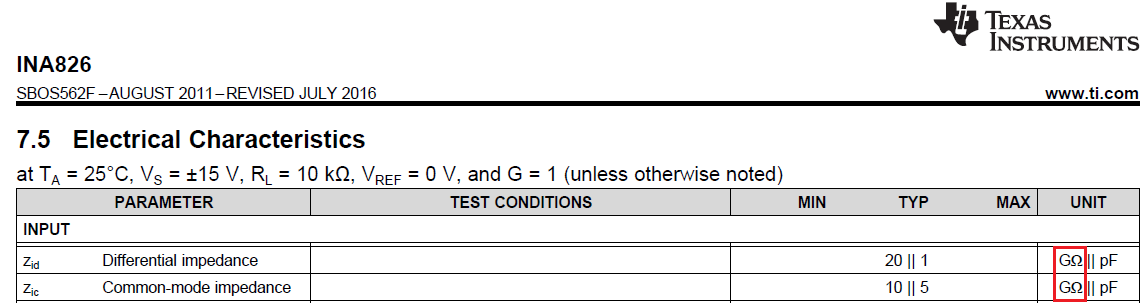
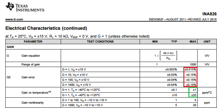
Therefore, I have to take the long term stabilty of the amplifiers gain into account.(rather than the offset voltage drift)

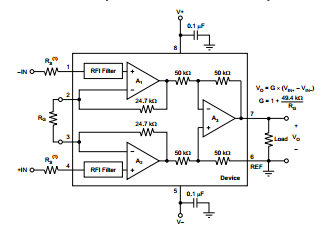
As you can see in the picture, (difference amplifier of the instrumentation amp) the ratios R6/R7 or R1/R2 should remain exactly the same.

Could anyone give me an approximate value of how much gain-drift we have to expect?
TemperatureRange: 0-70°C
Load: no Load (input of voltage buffer)


Best Regards and thanks in advance,

Achim Schäfer

  • Achim,

    First of all, INA826 is NOT a difference amplifier shown in your diagram but rather instrumentation amplifier shown below:

    The difference between the two is important because unlike difference amplifier, the input impedance of instrumentatiion amplifier is very high - see below.

    As far as your question regarding the temperature gain drift, it depends on the gain and is specified in the datasheet to be:  

    for G=1, the maximum gain drift is +/-1ppm/C while for higher gains it is +/-35ppm/C  (see below in green box) - these datasheet limits do NOT include error due to external gain setting resistor, RG. 

    The temperature gain drift is independent of the initial gain error and thus long term gain shift.  Like with most of our datasheet specifications, the maximum life time gain shift in INA826, which represent 10 years of constant operation at room temperature (87,6000 hours), is less than the maximum specified initial gain error: +/-0.015% for G=1 and up to +/-0.15% for higher gains - see below in red box.

  • Thank you for the prompt answer! The difference amplifier I was talking about is the one INSIDE the INA826. The ratios of the 50k resistors
    may drift during lifetime, what causes an error. (I'll implement the INA826 at G=1 | without the gain resistor)
    According to my understanding, I have to consider a maximum error of +- 0,015% if I run the INA826 for ten years at 50-60°C an a non-negligible
    humidity (50-80%)? (Your previous answer, which was very helpful so far, takes only room temperature for long term use into account.)

    Actually the drift of the gain is not our real problem, but the shift it causes for the CMRR. In the following formula t is the REAL ratio of the 50k resistors and Ad=G.

    Ramón Pallás-Areny and John Webster (1991)

    Equation 3
    Thanks again for your help.
    Cheers,
    Achim Schäfer

  • Achim,

    The matching of the initial values and TC coefficients of the gain setting resistors inside INA826 is the main cause of the gain initial error and drift as well as what limits the CMRR spec and for that reason all of those resistors get laser trimmed at the wafer level. The initial maximum error of +/-0.015% for G=1 applies only at the beginning of life of the product and after that it may shift by up to +/-0.015% at the end of life.  Thus the total error after ten years of operation at 25 deg C could be as high as +/-0.03%.  However, since a typical gain error of 0.003% equals to one standard deviation, its maximum value of 0.015% represents 5-sigma and thus according to Normal Gaussian distribution probability function only one out of 1.7 million units may be found at its max/min value.  The same is true of the long-term shift – only one out of 1.7 million units may shift by +/-0.015%.  For that reason, the probability of any INA826 unit after ten years at 25 deg C having a gain erro of +/-0.03% is miniscule - one in 2.89 billion (1/1.7e6*1/1.7e6).  However, all these considerations do not include the effects of the humidity which may cause an additional stress resulting in higher shift (we do not have such data to share). 

    The life of the product is governed by the Arrhenius equation - a simple but remarkably accurate formula for the temperature dependence of the reaction rate constant of a process:

    Process Rate (PR) =  Ae-(Ea/kT)


    Using the above equation, you may find out that ten-year life of the product at 25 deg C is equivalent of 4 years at 65 deg C and just 6 months at 100 deg C. Thus the maximum shift in the gain error of +/-0.015% will occur sooner at the elevated temperature and the same is true regarding all other specs like CMRR – see attached Long-Term Stability presentation.

    Long-Term Stability.ppt


  • Dear Marek,

    thanks again for your comprehensive answer.
    There is now only one question left concerning the acceleration factor. (e.g. page 21 of your presentation)
    You are calculating with an Ea of 0.7eV (in your PP) what is something like a empirical value based on historic data.
    I've seen in other resources that 0.5eV < Ea < 1ev are feasible values.
    I derived the Ea from your calculation (ten-year life of the product at 25 deg C is equivalent of 4 years at 65 deg C) what yields to a Ea of ~0.2eV.

    Since this is the exponent, we have to know this factor pretty good.
    What is a reasonale value for the INA826?

  • Due to momenta exchange between the current-carrying electrons and the host metal lattice, aluminum ions can drift in the direction of the electron current.  Due to the presence of flux divergence centers, vacancies start to cluster, clusters grow into voids, and the voids can continue to grow until they block the current flow in the aluminum. Thus, the current is forced to flow through the supporting barrier layer and/or capping layer; the resultant increase in resistance leads to device failure. Since this is a mass conserving process, accumulations of the transported aluminum ions increase the mechanical stress in supporting dielectrics, and may eventually cause fractures and shorts to occur. Based on several industry-wide empirical analysis, it was determined that for the failure rate to be constant regardless of operating junction temperature, an activation energy of 0.7eV should be used in conjunction with Arrhenius equation.  Thus, the industry consensus is that the proper activation energy for aluminum corrosion is in the 0.7-0.8 eV range and that is what you need to use in calculation of the acceleration factor (AF).  

    In your back-calculation of the activation energy, Ea, you assumed that the product will last 10 years at 25C vs 4 years at 65C but this is not correct.  The error comes from the fact that what you have used in your calculation is an ambient and not junction temperature. However, because of the self-heating caused by the power dissipation inside the package, 10-year-life of the product is expected to occur at 53 deg C (326K) junction temperature and that is the temperature you have to use in the above calculations instead of ambient of 25 deg C.