This thread has been locked.

If you have a related question, please click the "Ask a related question" button in the top right corner. The newly created question will be automatically linked to this question.

OPA356: Back-termination

Part Number: OPA356

In the Application Information Section of the datasheet for the OPA356 it states :

"The OPAx356 output stage is capable of driving a standard back-terminated 75Ω video cable. By back-terminating a transmission line, it does not exhibit a capacitive load to its driver. A properly back-terminated 75Ω cable does not appear as capacitance; it presents only a 150Ω resistive load to the OPAx356 output."

What does the term "back termination" mean?

  • Nigel,

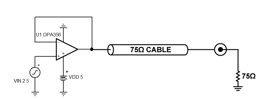
    A back-terminated 75Ω video cable means that the termination is placed at the other end of the transmission line.  Therefore, the resistive load presented to a driver is the sum of the cable resistance and 75Ω termination load - a total of 150Ω  (see schematic below).

  • Hi Nigel,

    Transmission lines have a specified surge impedance, also called the characteristic impedance. In this case, the line being referenced has a Zs of 75 Ohms. The line impedance Zs, in its most ideal form, is simply equal to:

    √ (L/C)   where L is the incremental inductance per unit length, and C is the incremental capacitance per unit length. Therefore, Zs is not a resistance, but an impedance.

     If the line length is a significant portion of a wavelength and it isn't terminated into a resistive load having a resistance equal to Zs, then it is possible to develop standing waves on the line. The standing waves have voltage and current maximas and minimas that differ from that measured directly at the output of the signal source - the op amp output in this case. Also, if the line is not terminated the impedance presented to the driving source is most often complex consisting of a resistive component and reactive component (R+jXL, or R- jXc). That can result in overshoot, ringing and even oscillation depending on what the load impedance presented to the op amp output represents. It can alter the video performance due to altered voltage levels and phase shifts.

    In order to provide a terminated transmission line environment different techniques are applied to circuits where transmission lines are involved. Some apply a shunt resistor to ground having a resistance equal to Zs at the end of the line. Another places a "back termination" in series with the source (op amp) output. Even if the transmission line does not see a terminated load equal to Zs at the end of the line any power reflected back down the line is absorbed in-part by the "back termination."

    One of the best methods to assure a terminated environment is to apply both the shunt resistor at the end of the line and the back termination at the input of the input (source end) of the line. A 75 ohm back termination resistor is added in series with the output, before the transmission line, and then at the end of the transmission line at the load a 75 ohm shunt resistance to ground is added. Very often the input impedance of the load is something much different than 75 ohms and adding the shunt makes the impedance much closer to that value. 

    Keep in mind that using a 75 ohm back termination resistor, and a 75 ohm load shunt resistor form a voltage divider. Visualize for a moment that the transmission line is removed and the resistors are connected together. This introduces a -6 dB loss, or a 0.5 V/V gain factor, which needs to be taken into account. Also, since the two resistors are essentially in series the total resistive load presented to the op amp output is 150 ohms.

    Regards, Thomas

    Precision Amplifiers Applications Engineering