This thread has been locked.

If you have a related question, please click the "Ask a related question" button in the top right corner. The newly created question will be automatically linked to this question.

OPA320: Photodiode amplifier settles in (relatively) long time

Part Number: OPA320
Other Parts Discussed in Thread: TINA-TI, LMH6644, TLV431

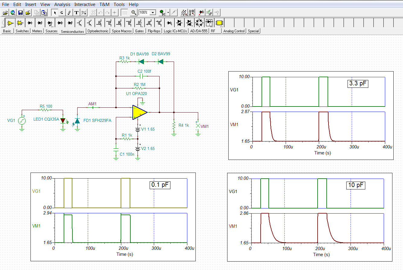
I have a very basic photodiode amplifier using an OPA320, connected like the following

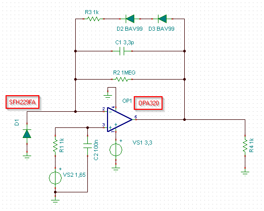
which exhbits a behavior that I can't completely understand.

The photodiode is filtered from visible light, and a nearby light source is a high current pulsed IR emitter (around 0.5 Amps) for a relatively short time, 28 us pulses over 225 us of period. I have a measure to take place when this IR source is OFF (yes, this is not the emission I'm measuring).

My problem is that besides I'm synchronized with the "disturbing" light (I generate it for another purpose), I need to measure a secondary tiny light level within 30-40 us after I turned this lighthouse off.
Note: this secondary signal isn't even "visible" at the output of this amplifier, since it needs further amplification.

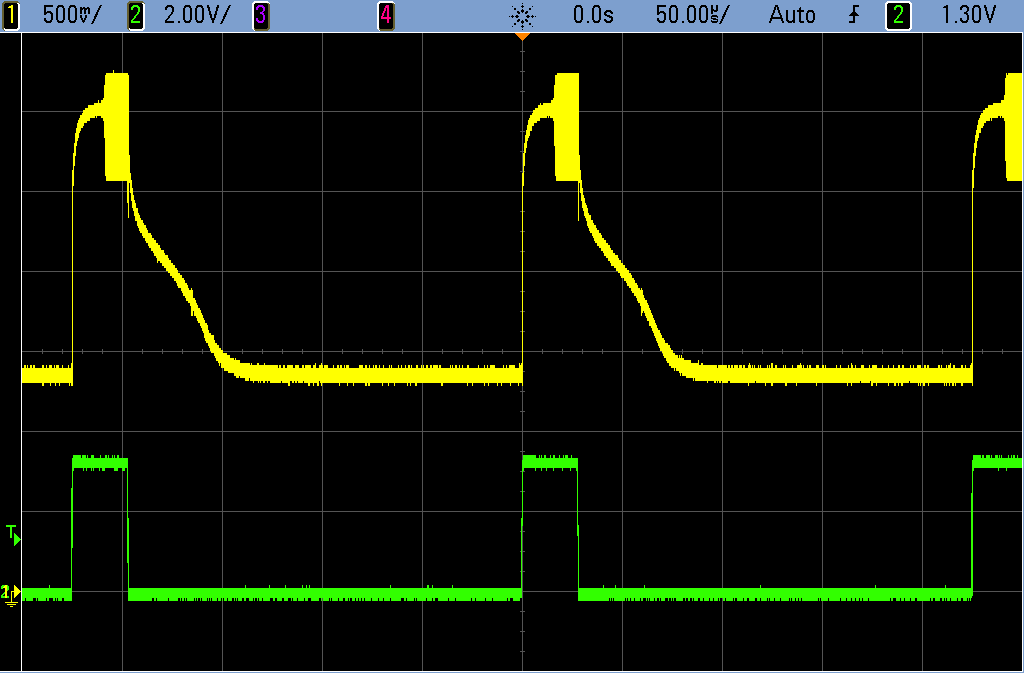
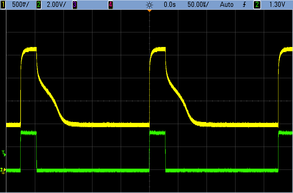
The circuit above is first limited to avoid saturation of the OA, even though with OPA320 this shouldn't be an issue (should come out of saturation way faster than my 30 us to a measure). I expected the level to take some time (microseconds?) to settle at the low light/dark level, after being dazzled, but what I obtain is something like this

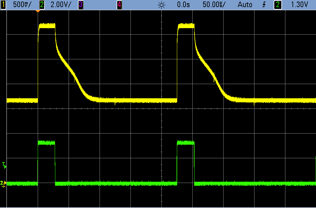
The yellow trace is the analog output, and the green one is the high power LED control (with a simple on/off control).

Why does the output take so long to settle at the dark level? What puzzles me more is the shape of the decaying curve, which isn't related to feedback capacitor.

I inherited this circuit from an older design, so I can't even explain why with some very similar setup it worked in the past, while I'm apparently unable to make it work!
The original circuit used also another classic scheme, with a discrete JFET stage inserted between the PD and the OA, but that doesn't change the output result of this amplifier.

  • Hi LucaMSB,

    Your OPA320 circuit appears straightforward so I went ahead and set it up in a TINA Spice simulation. Testing the circuit in various ways with TINA indicated that the output tailing off characteristic is related to the feedback capacitor value. Below, you can see the results for C1 equal to 0.1 pF, 3.3 pF and 10 pF. Since C1 is shunted by the series combination of R3 and the two series diodes they may be adding a non-linear capacitance across it. 

    I've attached my TINA circuit should you want to try simulations.

    Regards, Thomas

    Precision Amplifiers Applications Engineering

    OPA320_transZ_01.TSC

  • Thanks Thomas,
    your simulation completes what I just sketched with Tina-TI.

    The feedback capacitor is involved in the descending signal, and I'm aware of that. We tried a few capacitance values, but that seem not to influence the "hump", just the exponentially descending component.

    Note this image, taken with an LMH6644 in place, and no feedback capacitor:

    As you can see here the part is prone to oscillation, and that's normal, missing a lower frequency stabilization pole, but that hunch is still there!

    We tried some different amplifiers, and we built a couple of circuits on different prototype boards, just to make sure we weren't wrong with something in the assemble. The results kept being the same ones.
    This lead me to think there's something with the SFH229FA, despite I can't understand exactly what. The chip is small and Its capacitance isn't that high; we tried also biasing it with a negative voltage on the anode (around -3V), to lower it... well, to no avail.

    Another hypothesis was on bandwith and response time: here's why I changed the OPA320 to an LMH6644 I had at hand, to have an higher GBW to start with. That changed nothing, as shown above (with the 3.3pF feedback result is mostly the same, just without oscillations).

    I'm quite puzzled.

    Thanks again,

    Luca

  • Hi Luca,

    I can't tell from the images exactly what the voltage range of the yellow output trace is. It looks like the vertical is 500 mV/div, but I am not sure where the 0 V reference marker for channel 1 resides. It may be obscured by the channel 2 marker.

    Is the output maximum voltage swinging close to the positive supply level? If it is hitting the positive output rail, then that might provide a clue.

    Regards, Thomas

    Precision Amplifiers Applications Engineering

  • Both traces have GND level on the lowest horizontal division marker; trace 1 (yellow) is at 500 mV/div.

    Yes, they come close enough to positive supply rail (3.3V), so if I can trust the data sheet, an LMH6644 should go a bit higher than 3V (...) and recover a bit better from overload (...)

    Anyway, my reference/virtual ground voltage comes from a TLV431, so I trimmed it from the original 1.65V to a lower 1.35V, and here's the result

    Traces are still on same lower division reference, output signal at 500 mV/div; amplifier is still one section of LMH6644 in this case. Oscillation is gone, the "wrong derivative" decaying curve is still there.

    The feedback capacitor is still missing, so what's included is BAV99 capacitance and parasite capacitances. The first should be moderate, after all, being the two diode junctions in series. Even the second should be low enough: the LMH6644 is in free air, with short loose wires (less than 6-8 mm).

  • Hello Luca,

    If the output of either of the op amps tested is hitting the rail, then there will be an overload recovery period. When the output hits the rail the op amp electrical characteristics can change dramatically. Often, the open-loop gain collapses, the bandwidth drops, noise increases and dc parameters shift. The degradation in performance can affect the amplifier's output linearity. That might explain the hump in the falling edge of the output waveform. If you decrease the input drive such that the output swing is less does the tailing edge characteristic improve?

    Is there any other load on the output of the op amp besides the 1 k resistor, such as a capacitor, cable, etc.?

    Regards, Thomas

    Precision Amplifiers Applications Engineering

  • Hello Thomas,
    evidently I'm clearly misunderstanding some parameter or behavior, since I'm still feeling like the amps are in what's supposed to be their operating range. Let me try explain.

    The BAV99 + 1K resistor feedback branch limits the output preventing saturation. This should happen as I expect, taking as an example the latest screenshot. In that case reference voltage is set a t 1.35V, so voltage on non-inverting node should be the same. The BAV99 series should start conducting quite well at a voltage around 1.3V, so when the output is at 1.35 + 1.3 = 2.65V it should safely clamp, and that is confirmed by the scope. An output of 2.65V, with a supply of 3.3V, should be far enough from overload/saturation on LMH6644 -- data sheet tells me the minimal output voltage swing is 2.8V at 3V supply, so I don't see a reason why it should lower with 3.3V supply.

    The second point is very interesting, just about what you're pointing. The amp output, in case of saturation/overload, can have temporarily a "hump" response. That's mentioned in LMH6644 data sheet, and at first I didn't see that graph, since I focused on OPA320, which is documented to have a different response. However, LMH6644 has a plot with output coming out from overload in 100 ns.
    The graph is specified with AV=+5, that can be the limit of my reasoning: may the feedback network, with its inherent pole(s) have influenced the response of the amp coming out of saturation?
    Could that 100ns distortion have been elongated for 50us (and more) by the limited bandpass? That I don't know.

    As a side note, OPA320 apparently has no "hump" in response, coming out of saturation, in its "Overload Recovery Time" graphs. Just decays/rises in a few hundred nanoseconds with a gain of -10, again I don't know or have the meaning to know what happens with a high-gain, band-limiting feedback network.

    I'm not at office right now, so I can't test the setup, but there's something more I remember from the measures. A week ago I disconnected the BAV99 branch, to see how the amp was recovering. I remember it took way longer to come out of saturation (around 40us and more, maybe), but I don't remember I've seen the hump that time (test was with OPA320).

    Now that poses a good challenge: if this simple output limiter avoids saturation, but delays settling, I will have to figure a better way to do it (...)

    To answer your question, the circuit has been separated from any further signal processing, so the 1K resistor is the only load (besides scope probe), soldered a few millimeters from the output (everything has been kept so tight to hate making new tests that need modifications...).