This thread has been locked.

If you have a related question, please click the "Ask a related question" button in the top right corner. The newly created question will be automatically linked to this question.

TLV274: Differential Opamp Configuration startup behaviour

Part Number: TLV274


Hi,

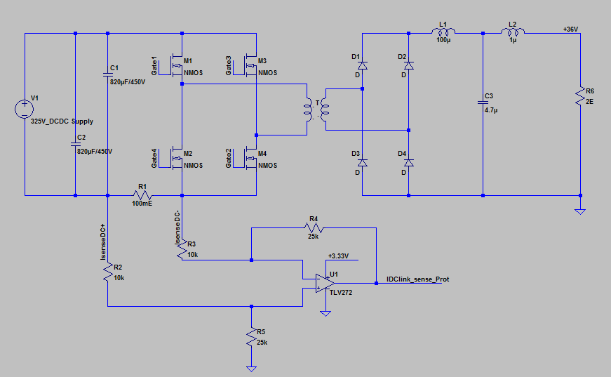
 I am using the TLV274 Opamp sensing in a differential opamp configuration as shown below.

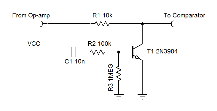
The output of this opamp is connected to a Comparator circuit which latches when Opamp output becomes more than the ref.

With the supply cap of the opamp being 0.1uF ceramic.

Problem: The opamp output as soon as the power supply switches on generates a spike.

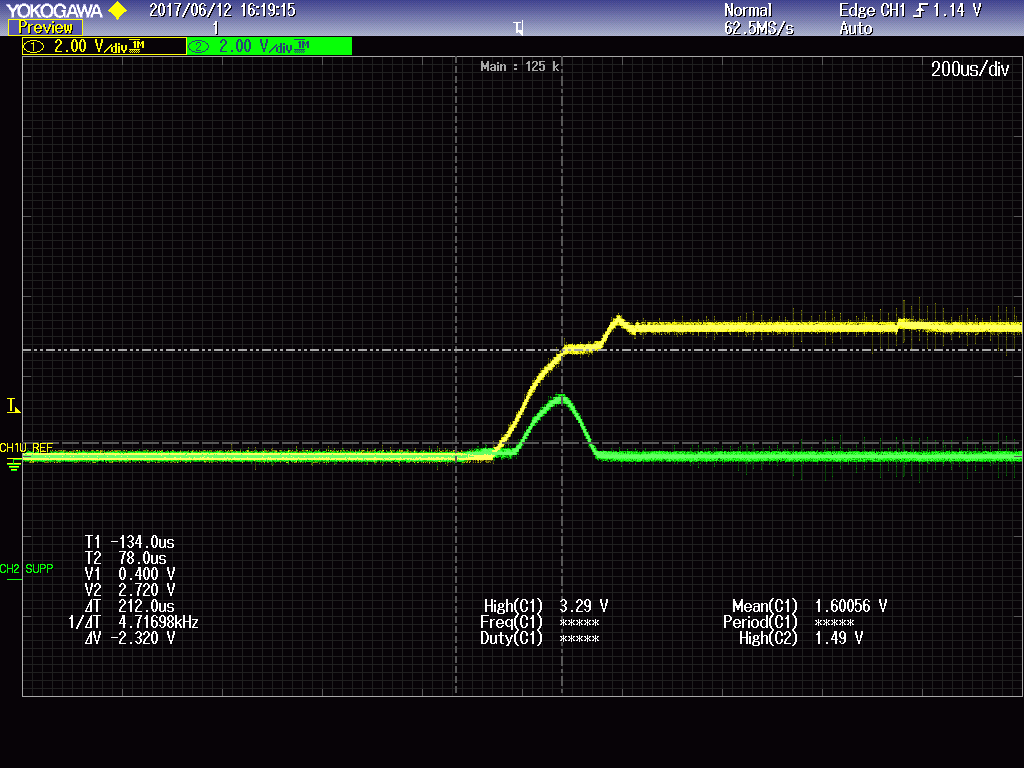
This is how the comparator inputs (OPamp output and Reference)look like.


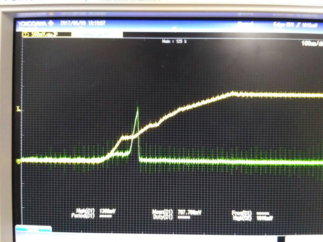
Yellow is the reference (The ramp in the reference is because while startup the power supply takes about 400us to reach the required supply of 5V) Scale is 0.5V/ div

Green is the opamp output(Scale is 0.5V/div)

The duration of the spike is about 50us

The peak of spike is 1.2V

Due to this spike the comparator begins to latch during the startup itself.

How do I mitigate this?

Regards,

Rajesh

  • Rajesh,

    During this pulse, I suspect VCC is less than 1.5V so the part is not at operational supply voltage. TLV274 has no mention of a "power up reset" that will make output predictable in power up. Either a change to a POR op amp, op amp with shutdown capability, or a power up masking circuit will be needed.

    Can you check input voltage and VCC during the pulse?

    Here is a sample mask circuit, that starts working as VCC gets to 0.6V so the TLV274 peak might not be fully eliminated.

    VCC needs to be clean because 500mV peaks on VCC could active the mask after power up.

  • Dear Ronald,

    thanks for the inputs

    I am attaching a few waveforms here.

    Yellow - Supply voltage

    Green - OPamp Output

    Wave form 1

    R250,R251 - 240k

    R252,R253 - 100k

    Wave form 2,

    R250,R251 - 25k

    R252,R253 - 10k

    Waveform 3

    R250,R251 - 2.5k

    R252,R253 - 1k

  • As I increase the value of the resistors keeping the gain constant the spike value increases.

    The recommended operating voltage for the opamp is 2.7V for single ended supply.

    and in waveform 1 the pulse starts reducing after the supply reaches 2.7 V
    May be the opamp is behaving as it is supposed to be after it reaches the recommended operating voltage.

    But I am stumped on how the increase in the values of the resistance affecting the peak of the spike.

    Any inputs on this?
  • Hello Rajesh,

    Ron is out of the office so I will help as best I can until he returns.

    Once the supply voltage reaches the minimum value and the internal circuitry becomes properly biased the device should behave as expected. Until then it is common to observe a glitch on the output of an op amp. Here are a couple blogs that may be of interest:

    e2e.ti.com/.../op-amp-supply-limits-are-they-critical

    e2e.ti.com/.../op-amp-supply-limits-are-they-critical-part-2

    Given that you observe a direct relationship between the magnitude of the glitch (voltage) and the size of the surrounding resistors it leads me to believe that this is current related. One potential culprit could be exaggerated input offset current during power up that creates an offset voltage with R250/251 that is ultimately amplified and appears at the output. Once the device reaches the minimum supply voltage and the internal circuitry is properly biased the input offset current will return to normal. Such a small input offset current would then induce an insignificant offset voltage when compared to the initial input offset voltage of the device. Another potential culprit could be that a current flows out of the output of the amplifier during power up and interacts with the feedback resistor, which appears as a load. This creates a voltage on the output. You could conduct a few additional experiments by changing the resistor ratios, but please realize that this will also change the gain of the circuit.

    Hope this helps!
  • Dear Pete,

     Thanks a lot for the reply.

    I could correlate your explanation to the problem.

    As a fix to the problem I've reduced the values of the resistances in the ladder. This made sure that the reference in always greater than the opamp out and hence could bypass the problem.

    But I am facing a peculiar problem now.
     Its not related to the startup of the opamp anyways.

    I am attaching the circuit configuration here

    I am sensing the current through R1 and is being sent to the microcontroller on the secondary side which has the microcontroller ground.

    So far so good.

    The circuit works and detects the fault coorrectly untill I connect a probe on the ground.

    The problem appears once I connect the probe's ground on the ground of  the opamp. The comparator downstream to the opamp sense output some how detects the fault.

    This problem doesn't untill the ground probe is connected

    Any inputs on this?

    Regards,
    Rajesh sura


  • Hello Rajesh,

    Is the ground node for the comparator the same as the ground node for the op amp?  

    Perhaps you could set up an o-scope with a trigger and capture the inputs/outputs of the comparator when you connect the probe ground to the amplifier.

  • Dear Pete,

     The ground of opamp and comparator are same.

    I am not able to connect the probe because as soon as I connect the probe the comparator latches.

    Chicken and egg sorta problem.

    Regards,

    Rajesh sura


  • Hello Rajesh,

    Thanks for the information. Can you reset the comparator while the probe is connected? Then attach a 2nd probe to re-create the event.

    To be clear, you are talking about an oscilloscope probe, correct? Where is the non-ground terminal of the probe (or clip) connected?