This thread has been locked.

If you have a related question, please click the "Ask a related question" button in the top right corner. The newly created question will be automatically linked to this question.

TLV9062: Power Up Timing Requirements

Part Number: TLV9062
Other Parts Discussed in Thread: TLV906X, OPA316

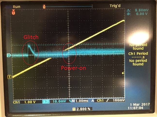
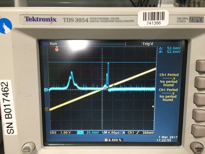
We have a design to restrict the current consumption of the TLV906x devices during inactive state. For this we plan to switch the power OFF when the signal conditioning is not to be done. The question is: What is the timing requirement on the power supply when ramped to 3.3V after which the OUT signal can be sampled by an ADC?

Is this parameter specified in the data sheet?

  • Hello Amit,

    We do not have a characterization for the timing requirement you are looking for. In testing, there is a power-on glitch that may occur and it is a function of the power supply's rate of increase. Thus, a greater rate of increase will provide a larger glitch, and vice versa. This occurs upon power-on because the internal transistors are not fully biased, and cause a violation with respect to the supply and common-mode voltages. An example shot is shown below.

    An alternative choice for your design may be the OPA316S with shutdown pin.

    Regards,

    Ramon Jimenez

  • Hello Ramon,

    I checked the OPA316 and for one Op-Amp the shutdown current is 1uA (MAX) which when translated to 12 OP-AMPS lead to 12 uA (MAX) which is a power drain on a coin cell. Also the enable time of 13 us may be too long.

    Alternatively, if I power up from 0V to 3.3V and wait for 1 us before starting sampling the OP-AMP output, would that be a sufficient time for the OP-AMP output to stabilize?
  • Hi Amit,

    To make sure I'm understanding you correctly, you are referring to waiting until the supply reaches the full 3.3V before waiting 1us to sample the output? Under these conditions, I'd say that would be sufficient time for the output to stabilize.
  • Hello Ramon

    Yes, that is correct. And will this 1us be guaranteed across min-typ-max, as the device datasheet does not have a parameter for the same?
  • Hi Amit,

    Unfortunately that is not something that I can guarantee as it is dependent on the power supply. The test data below shows the output with respect to a 50us power supply ramp rate. It stabilizes at a little over 2V and at 3.3V the output is still stabilized. My concern is if the ramp rate is too fast, then it may delay that time further and it may not be stable when it reaches 3.3V. With the test data I've shared it is fine 1us after the 3.3V point for these two tests, but again this cannot be guaranteed for every condition. 

    Also, how often will this be turned on? With 12 on the board it can have a large current drain on the battery when power cycled to sample, and this can drain the battery even faster over time.

    Regards,

    Ramon Jimenez