This thread has been locked.

If you have a related question, please click the "Ask a related question" button in the top right corner. The newly created question will be automatically linked to this question.

OPA4277: Current consumption calculation

Part Number: OPA4277

Dear Team,

Can you please share me how to calculate current consumption information of TXB0108PWR.

Regards,

Prasanna G

  • Dear Team,

    In above post there was a typo, please consider below query

    Can you please share me how to calculate current consumption information of OPA4277.

    Regards,

    Prasanna
  • Prasanna,

    I'm not sure how to understand your question. If you meant to ask about the total quiescent current, it is given (per channel) to be typical 790uA and max 825uA at 25 deg C while 900uA over -40C to 85C temperature range; thus, a total maximum quiescent current for quad version would be 3.3mA at 25C and 3.6mA over entire specified temperature range.  

    If you really meant to ask about the power dissipation in IC, you have to include quiescent current AND any output current loading but to answer would require that you provide us with detailed schematic showing exact loading conditions.  Also, please review TI Precision Lab videos/lectures covering the topic of power dissipation under following link - it will most likely answer most of your questions: 

  • Hello Team,

    Here i needed operating current , i.e we have 12V input to this device pin VS but i want know how much current this IC takes from 12V during operation time.

    since our 12V generated from regulator which can supports max 500mA, So is voltage is shared with 10 number of OPA4277 IC, So this is enough or not is my question

    Regards,
    Prasanna G
  • Prasanna,

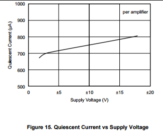
    OPA4277 quiescent current (where Iout=0) is not a strong function of supply voltage and it is shown in the graph below.  Since you have not provided schematic, I presume that by operating current you mean quiescent current and if so on 12V single supply you could power from 500mA regulator 173 OPA4277 quads: 500/(4*.72).  If you need additional help, please provide circuit schematic showing power supplies, input voltage and component values especially in this case any resistive loading.

  • Hello Marek,

    Usually "total current = quiescent +Operating current "So here i wanted to know total requirement of 1 OPA4277 ,

    i am having 12V@500mA regulated ouput, So i want to how many OPA4277 can i able to work(connect).

    Don't we require to consider operating current.

    Regards,
    Prasanna G
  • Prasanna,
    According to your definition of the operating current, it includes loading effect, Iout. But I am not sure how do you expect us to know Iout since thus far you have not shared your circuit schematic. Having said that, as long as the peak loading is less than 10mA per channel, you can easily drive 10 OPA4277 from your 500mA regulator.
  • Hello Marek Lis,

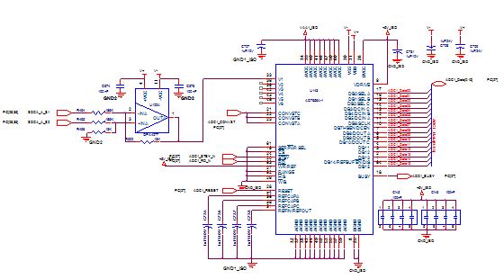
    I  attached my schematics, here OPA4277 connected to 10pF load , 

    Request you to share me the current requirement at +VCC of OPA4277.

    Note: V+=12V 

    Regards,

    Prasanna G

  • Hi,

    Awaiting for the response.

    Regards,
    Prasanna G
  • Prasanna,

    Your schematic is not legible (too low resolution).  Also, I see you use a difference amplifier at the front-end but you do not show any input voltage (the inputs float) - the input signal will cause different loading across the resistors and to calculate the current you must know the input voltage.

    Having said that, capacitors do not draw dc current and for ac capacitive loading you would first need to determine its equivalent impedance,   , and then calculate the ac current based on the actual signal voltage (magnitude and frequency) - thus more information is needed.

    For more information, please review the details regarding calculation of power under following link: 

  • Hello Marek Lis,

    I  attached my schematics, here OPA4277 connected to 10pF load ,

    Request you to share me the current requirement at +VCC of OPA4277.

    Note: V+=12V

    Regards,

    Prasanna G

    opa4277.pdf

  • Prasanna,

    According to your schematic, OPA4277 loading consists of 13k feedback resistor,Rf, and track-and-hold amplifier inside of AD7658, which should be negligible.  Thus, for 12V supply voltage, the maximum output current, Iout, would be less than 1mA (Iout<Vout/Rf=12V/13k=0.923mA).  

    Therefore, the total maximum current consumption per channel would: I_total_max=IQ_max+Iout_max=0.9mA+0.923=1.823mA.

    This means that the total maximum current consumption per quad would be less than 7.3mA (4*1.823mA).

    Therefore, ten of OPA4277 IC's would consume the maximum total current of less than 73mA and thus your 500mA regulator should have no problem to power all of them.

  • Hello Marek,

    Thanks for the valuable information.

    In OPA4277 , we provide V+ and V-, So in this case 7.3mA from each of the supply separately or 7.3mA form both supply(7.3/2 from each supply).

    Regards,
    Prasanna G
  • Prasanna,

    In order for the current to flow, the circuit must be closed between the positive and negative supplies. Thus, the total current coming out of the 12V 500mA regulator will be sunk by the negative supply (current cannot evaporate) and then re-circulated back into negative terminal of 500mA regulator - therefore, this is the same current so do not count it twice. In other words, the total current sourced by 12V positve supply to ten OPA4277 will be 73mA and the same -73mA will be sunk by -12V negative supply and sent back thru ground loop to positve supply.  Of course, for this to work the negative supply must also be able to sink at least 73mA current.

  • Hello Marek,

    Thank you so much for you brief explanation.

    Regards,
    Prasanna G