This thread has been locked.

If you have a related question, please click the "Ask a related question" button in the top right corner. The newly created question will be automatically linked to this question.

DRV425: What is the minimum resolution of DRV425 ?is it possible to mesure a current of 1 mA (magnetic field of 0,1 uT) ?

Part Number: DRV425
Other Parts Discussed in Thread: , ADS1262, ADS1278

Hello,

A custumer asked us a contactless sensor which can detect whether a current of 1 mA is flowing into a cable.

The measuring range is 10uT : 0,1 uT.

The minimal resolution is not given in the datasheet of the DRV425.

Is it possible with this sensor to measure a magnetic field of 0,1 uT ?

I know I will need a shield to remove the earth magnetic field around 50 uT and the external other influences.

Regards,

Nicolas 

  • Nicolas,

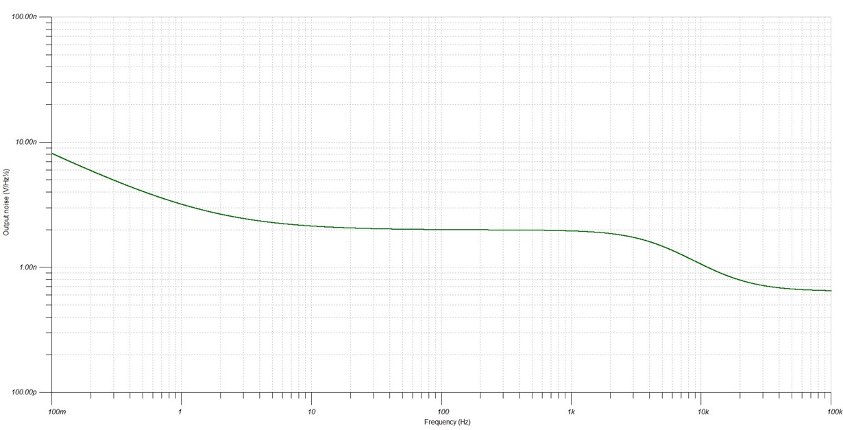
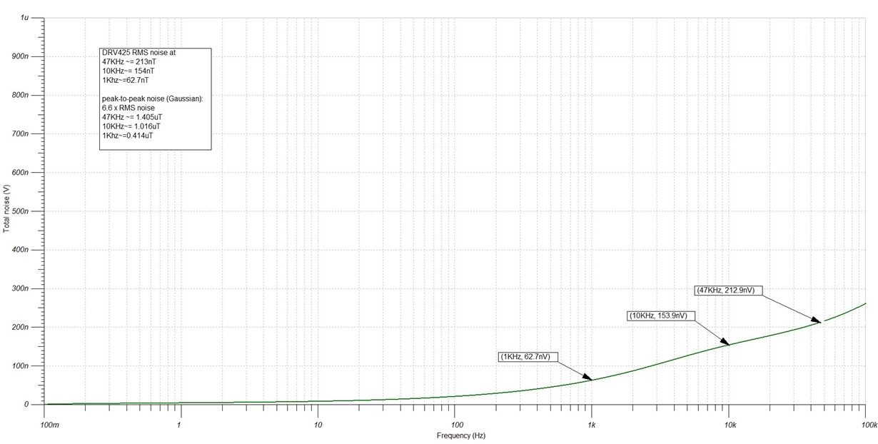
    I believe this is possible but the biggest limitation you will have is noise.  You can average the noise out and this will limit your bandwidth.  What bandwidth are you looking at achieving. I have a replicated the noise density plot generated in TINA spice to help with the noise calculation with the expected noise at the bandwidth of interest.  I also have the results in the RMS noise and have plotted a few points for your reference.  You may want to order one of our DRV425EVM to experiment with it.

  • Hello Javier,

    thank you for your precisions.

    The bandwidth is 10 Hz.

    Your plots are about the noise generated by the DRV425 ?

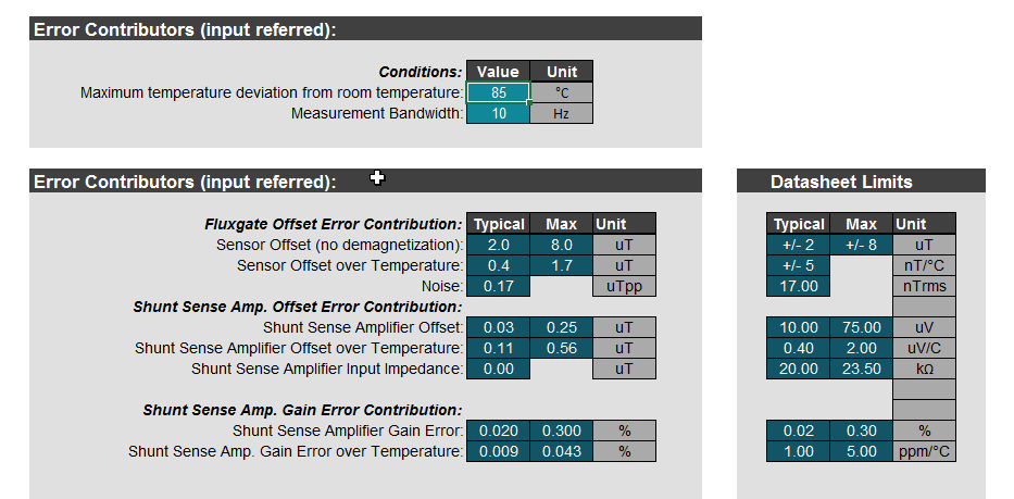
    With the DRV425 System parameter calculator, the Noise is calculated at 0.17 uTpp.

    I attached 2 files with the parameters.

    What does it means ?

    Is is relevant compared to your simulation with TINA spice ?

    Regards,

    Nicolas

  • Nicolas,

    The estimate I got was graphical from the noise density plot on the data sheet. The estimate of noise on the system calculator is based on a equation representation of the noise function over frequency. The both are estimates and match closely. The system calculator is much easier to manipulate and should be a good guide for what you are doing. This is a little above what you are looking for resolution but I believe you can get there.
    Can you please tell me how you are going to make the measurements. I can try to mimic in my lab and give you some results. I have a 0 Gauss chamber where I can shield all external magnetic fields. Are you planning to use a larger R-shunt than the number you provided above? Our current EVM R-shunt value is 100 which will give you a larger gain.
  • Hello Javier,

    So the aim is the measurement of a current flowing into a wire.

    The current measurement range is [1;50] mA inside the wire.

    The wire axis is at a distance of 1,5 mm of the sensor axis (just above the sensor).

    1 mA current flowing inside the wire will generate a magnetic field of 0,13 uT at 1,5 mm.
    50 mA current flowing inside the wire will generate a magnetic field of 6,57 uT at 1,5 mm.
    So the magnetic field measurement range is +-  7,5 uT (15uT).

    That give us using 7.3.1.4 Magnetic Field Range, Overrange Indicator, and Error Flag  equation 3 of the datasheet a Rshunt of 3,3 kohm.

    Is narrowing the field magnetic measuring range will reduce the noise ?

    To reduce the noise, a bandwidth of 10 hz is chosen.

    We plan to use a shield to reduce as much as possible exterior magnetic field, especially earth magnetic field, with at least 39 dB of attenuation.
    So we will have 6,3 nT of perturbation due to the earth magnetic field. 
    The shield will be cylindrical or spherical and uses material witha mery high permeability like mu-metal for example.

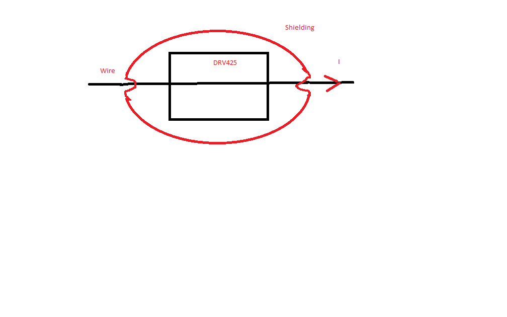
    Here a picture of what we plan to use :

    The shield is composed of two part, so it can be open to put the sensor in the middle and then closed the shield. 
    The shield is like an egg around the sensor.with two hole to let the wire go through.


    It will be very helpful if you can minic tat in your lab.


    Best regards,

    Nicolas


  • Nicolas,

    We made some lab measurements and got noise levels under the numbers in the parameter calculator.  We did the measurements with the 3458 meter sampling at 10Hz.  How do you plan on measuring at lower bandwidth.  ADC sampling?  Averaging?  Analog filter?  I can do some of these measurements in the lab but I think you can get the desired levels you need. 

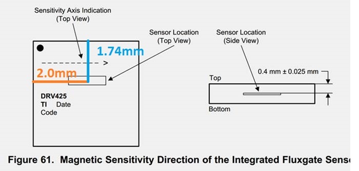
    The biggest concerns I would have is the exact mechanical placement and complete shielding of external fields.  There is some error in the sensor location inside the package.  If you are calibrating this for offset and gain you can get better results.  All measurements in the diagram are +/- 0.025mm.

    Also the routing of the supplies and the currents can play a part as the IQ of the device is typically 6mA.  Routing and calibration of the offset will help reduce this influence of this.  Routing the supply currents parallel to the axis of sensitivity will reduce the field seen by the supply currents.

  • Hello mr.Contreras,

    thank you for your quick answers.

    We though about averaging, yes.

    What do you mean with " the 3458 meter " ?
    Could you share the result of your lab measurement ? It will be helpful
    because the excel calculator give me a noise of 0,17 uTpp (60 nTrms) and the minimum is 17 nTrms.

    We want to measure a magnetic field around 100 nT.


    Thank you for the tips to improve as much as possible the precision of the measure.

    Temperature should also be calibrated.

    About shielding, i am unexperimented in magnetic shield, so do you know reference, or white paper about it ?

    Is Texas Instrument already release an application note about measuring very low current ?

    Regards,

    Nicolas
  • Nicolas,

    Please excuse my delay.  The 3458 is a meter that was used in my lab.  The is a high accuracy meter where I can control the number of power line cycles it measures.  Since my PLC is 60Hz in the US I made measurements with 6 PLC which is equivalent to measuring over 100mS.  I can get more lab measurements and describe the complete setup.  I currently have three measurement options.  If you have a preference please let me know.

    • Use the HP3458 meter and get values that are averaged over 100mS
    • ADS1262EVM and measure with 10 samples per second.  The ADS1262 is a delta-sigma has internal filters for higher frequencies.
    • ADS1278EVM and measure at a higher sampling rate and average over 100mS with post processing.  The ADS1278 is also a delta sigma that can sample at a higher rate.

    The data collection will not be an issue and I believe you will be ok with the results.  The biggest concern is the shielding. 

    The shielding is where you need to spend some more investigation and design.  The two issues I see is the contact between two pieces of ferromagnetic material not being as clean as can be.  If the surfaces do not make good contact throughout the entire surface area it will severely degrade your shielding.  The other issue is the permeability of the material.  The higher the permeability the easier it can get saturated but the better the shielding.  Also the thicker the material the better shielding and the larger value the material will saturate.  We do not have any white paper or application notes on this.  I can assist you through your design process.

    A question I should have asked previously.  Are you using magnetic sensing due to voltage concerns?