Other Parts Discussed in Thread: XTR111
art Number: XTR111
Hi team,
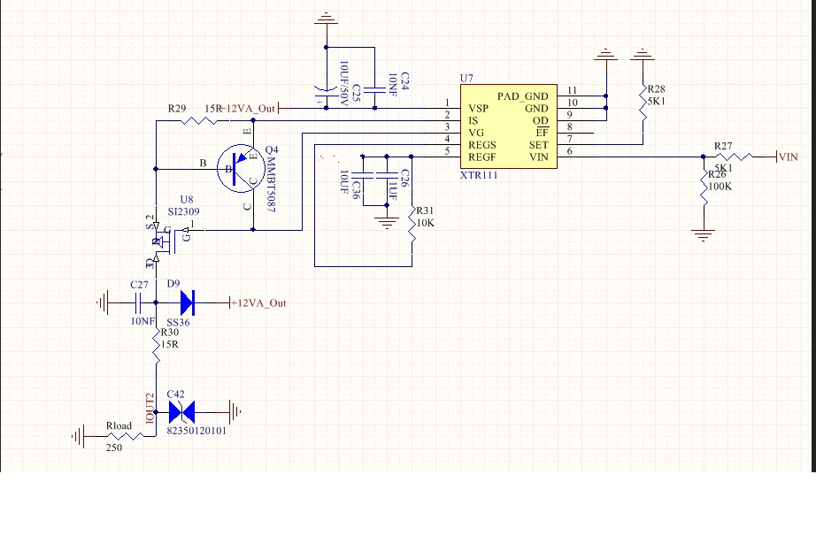
The customer is using XTR111. VSP is 12V. VIN is from 1V to 10V. His schematic is in the attach.
Is there any issue for his schematic?
Best Wishes,
Mickey Zhang
Asia Customer Support Center
Texas Instruments