This thread has been locked.

If you have a related question, please click the "Ask a related question" button in the top right corner. The newly created question will be automatically linked to this question.

LMH6514: Question for 200ohm input impedance in datasheet

Part Number: LMH6514
Other Parts Discussed in Thread: THS4551, THS7530, LMH6518, LMH6629

Hi team,

A customer reviews LMH6514 for VGA. The input of VGA will come from other differential Amp or sonar sensor.

-. In datasheet, they see a sentense of "200ohm Input Impedance". Can you explain how to match the impedance from Senor/Amp (for example, 50ohm) to the 200ohm of LMH6514 input?


-. In addition, can you recommend the proper devices for below siganl path? (The condition is to use 5V single supply for Amps and the multiple Amp stages is availabe for over 100dB gain.

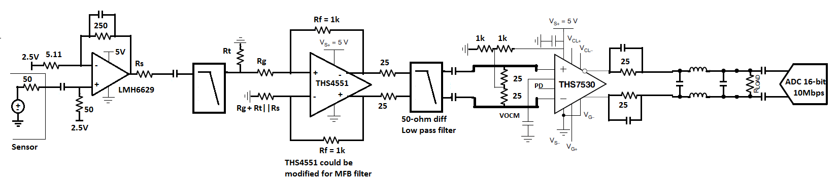
      Sensor -> Diff. Amps(THS4551 and ?) -> Filter(standalone device?) -> VGA(LMH6514 and ?) -> ADC(16bit/10Mbps)

Thanks,

Sam Lee

  • Hi Sam,

    Would it be possible to know what is the frequency band of interest the customer is looking at? From the ADC (16 bit/10Mbps) spec you have provided, it looks like the customer's frequency of interest is < 5MHz. If that is the case, it is important to note that the LMH6514 may not be able to meet the application because of the low frequency inductive roll-off required for Class A output stage biasing. If you look at Figure 48 in the LMH6514, it shows the low frequency roll-off for different value inductors. Higher the value of inductors, lower is the cut-off frequency.

    I think a more suitable part for the customer's application is the the THS7530 which is a continuously variable gain amplifier. The LMH6518 could also be used for their application by turning OFF the auxiliary gain stage.

    1. To answer your first question, I think it would be advisable to switch to THS7530 (or LMH6518). For matching to the VGA input impedance, you could use a resistance in parallel to the input that gives the input impedance as required by the filter termination. An example circuit using the THS7530 is given below for 50-ohm input and output low pass filter design.

    2. For the second question, do you happen to know whether the sensor input is single-ended or differential? Also, it would be helpful to get the frequency band of interest. If the sensor input is single-ended, I would recommend using a low noise amplifier like the LMH6629 at the front-end with high gain that sets the SNR of the signal-chain. It can then by followed by the THS4551 with 10V/V gain that does single-ended to differential output driving the VGA (THS7530). A block diagram of the circuit for 50-ohm sensor input is as shown below.

    Best Regards,

    Rohit

  • Hi Rohit,


    Thank you for your answer. The BW will be under 1MHz, and the sensor output is differential, so all path are handled with differential. For the impedence matching, if they should match a specific impedance (not 50ohm), can you explain how to match the impedance?


    Thanks,

    Sam Lee