This thread has been locked.

If you have a related question, please click the "Ask a related question" button in the top right corner. The newly created question will be automatically linked to this question.

INA240-Q1: Question about evaluation result

Part Number: INA240-Q1
Other Parts Discussed in Thread: INA240

Hello,


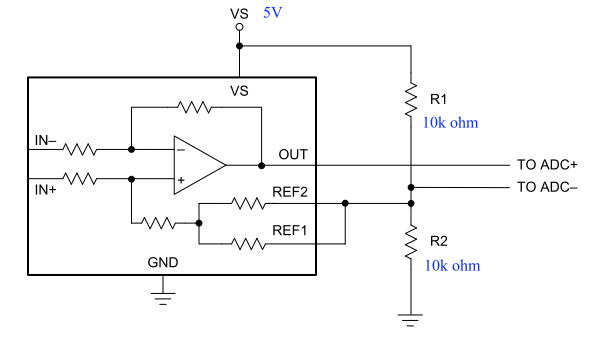
Customer evaluated INA240A1-Q1 using INA240 EVM.


Please refer evaluation circuit of attached file.

They input sine wave to IN+ and IN- and same waveform appears to ADC- with IN+.

INA240A1.pdf

Please advise if this is normal behavior of INA240.

If it is normal, please advise the reason why the same sine waveform appears to ADC-.


Best Regards.

  • Hi Toshio,

    Thank you for posting on the E2E Foruns,

    Yes, the measurements taken represent correct operation. This is due to internal bias currents as spec'd in the datasheet and the reason a differential measurement is required.

    Note however that, if the required reference is 1/2VS, REF1 can be directly tied to GND and REF2 to VS. The chip has a matched internal divider. External resistors are only required should VREF be a different value from VS/2.

  • Hello Carlos-san,


    Customer is evaluating INA240A1-Q1 with following circuit using INA240A EVM and gain seems to smaller than 20 (I could not get detail of measurement data yet.)


    I want to confirm following understanding is correct or not.


    Best Regards.


  • Hi Toshio,

    The correct equation is  V(ADC+) - V(ADC-) = (20*[(IN+)-(IN-)]).

    The gain will depend of the input/output signal. There is some attenuation at high frequencies due to the slew rate of the amplifier. I can comment further if you are able to provide some waveforms.