This thread has been locked.

If you have a related question, please click the "Ask a related question" button in the top right corner. The newly created question will be automatically linked to this question.

OPA2690: Single ended to differential converter

Part Number: OPA2690
Other Parts Discussed in Thread: TINA-TI, LMH6552

Hi,

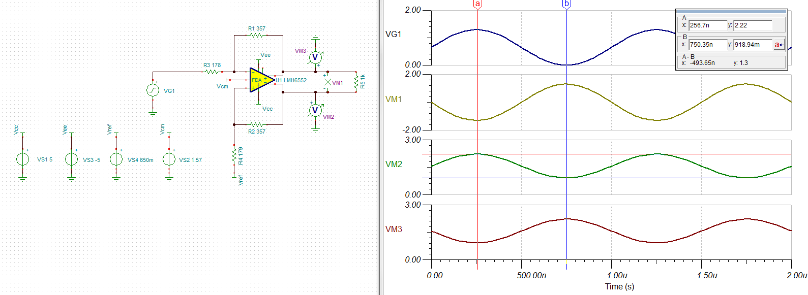
I have an unipolar signal with a swing between 0V and 1.3V and I need to convert it in differential (Common mode 1.575V +/- 0.675V on each output). I'm trying to design a circuit to do this (I want for 0V in input,  positive signal output at 2.2V and negative at 0.9V and the opposite for 1.3V).

I designed the circuit below. It seems to work correctly but it is not perfectly equilibrated. For exemple, I have 2.2V / 0.9V in one output and 2.22V / 0.9V in the other so I have an offset of 20mV in the differential output.

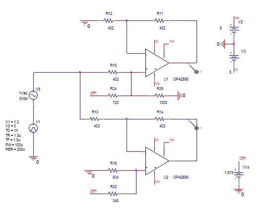
Is sombody have a better circuit or a way to modify my design to be more equilibrated?

Thanks a lot

Regards

Matthieu Baque

  • Hi Matthieu,

    Have you considered using a fully-differential amplifier (FDA) for your application? I think the application that you are describing can be accomplished using an FDA like the LMH6552. I have attached a brief TINA-TI schematic that should work for what you are trying to do. Here is the TINA-TI schematic for the same:

    LMH6552_FDAschematic.TSC

    Best Regards,

    Rohit

  • Hi Rohit,

    I didn't consider a fully diferential amplifier because I'm not familiar with it but it seems to be a good idea.

    In your schematic, the only black point is that I don't have any 0.65V in my design. I just have the 1.575V.

    Is there a way to avoid it?

    Thanks Matthieu Baque

  • Hi,

    I maybe have a solution. Regarding my input signal, I can modify it to have 0V 3.15V instead of 0V 1.3V. In this case, I can modify your schematic with 1.575V instead of 0.65V and R3=R4=433 Ohms.

    Could you tell me if you see any isssue building this schematic; please? I ask about that because in this case I have a gain less than 1.

    Thanks

    Matthieu Baque

  • Hi Matthieu,

    Yes. It is possible to modify the schematic as you have mentioned and I don't see any issues. However, I would recommend you to test your schematic in TINA-TI and make sure the circuit works correctly.

    Best Regards,
    Rohit