


Hi,
I have assembled the transimpedance amplifier with OPA847 for balanced homodyne detection. Feedback resistance 4.3 kOm, feedback capacitance(with parasitic capacitance of feedback resistor) 0.4 pF. The scheme is:

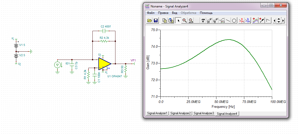
To simulate frequency response I used the next model:

According to TINA the square of gain-modulus versus frequency for my scheme is shown here:
However the measured gain differs from calculations in the frequency range 0-30 MHz. Red line shows approximation line from my theoretical model.

What is the reason for the discrepancy? What is missing in calculations?
I used Hamamatsu S5972 photodiodes with reverse voltage 13 V.


