This thread has been locked.

If you have a related question, please click the "Ask a related question" button in the top right corner. The newly created question will be automatically linked to this question.

AMC1100: Current Measurement

Part Number: AMC1100

Hello,

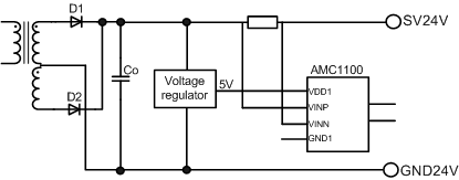
I would like to use the AMC1100 for output current measurement of an isolated DC/DC converter. At the datasheet is shown, that the high-side analog ground (GND1) should be connected with the end of the shunt resistor, which is connected to the negative input of the AMC1100 (VINN). I have an auxiliary 5V supply at the secondary side of the converter.

My question: I'm not sure if the ground of that 5V supply, which is the same ground as the "normal" secondary ground, should be connected with GND1, or is the 5V supply only connected to VDD1 like a floating supply?

Thanks :)

  • Hi Christoph,

    You would need to connect GND1 of the AMC1100 to the return of the 5V supply you connect to VDD1. You would have to provide more detail regarding your "normal" secondary ground before we could make any definitive statement about how that refers back to GND1 of the AMC1100. If your normal secondary ground is the same point electrically as the bottom of your shunt, that should be fine. If you are doing a high side current shunt measurement, you would need to float the 5V source.
  • Hi Tom, 

    Thanks for your answer.

    The "normal" secondary ground is the same as the ground of the ouput voltage of the converter. I have a high side current shunt measurement, therefore it's not the same point electrically as the bottom of the shunt. 

    So I need to float the 5V source, that mean's only connecting the VDD1 to the 5V?

  • Hi Christoph,

    You might need a completely isolated supply in this case.  Relative to the bottom of the shunt, which ties to GND1, VDD1 needs to be +4.5V to +5.5V.   What is the voltage difference between your normal secondary ground and the bottom of the shunt? 

  • Hi Tom,

    Okay I understand. The voltage different should be nearly 24V. I've added a simplified version of my secondary circuit.

    Beside the solution with that completely isolated supply, I can change the arrangement to a low side current shunt measurement?!

  • Hi Christoph,

    The circuit as drawn above would not work. Assuming you tie GND1 to VINn, you would have 5V at VDD1, but you would be exceeding the common mode voltage on the inputs (VINp would be @ 24V, VINn would be 24V - VRshunt). If you go with low side measurements, that would be fine, just move the shunt to GND24V along with GND1 and VINn.