This thread has been locked.

If you have a related question, please click the "Ask a related question" button in the top right corner. The newly created question will be automatically linked to this question.

OPA564: Power Sequencing, Vdig and V E/s

Part Number: OPA564

Hi,

I currently use opa564 with no issue, I use +/- 12VDC for the Vs and -vs.
For Vdig I use resistor divider of 1K and 500 Ohms connecteed to -12Vdc, which will create around -8Vdc on the Vdig.

I didn't take care of power on sequencing so far. But I would like to implement one.
What is th ebest way to do it ? Will a bigger cap on the analog power supply wil be suficient ?

Ad for the v e/S (enable/shut down) , what  is the range for shutdown logic if I use  +/- 12Vdc . If I look at the datasheet , range is -12V to (-11.2).

How do you implement this  practically ?

Thank you

  • Hello Siauhwa,

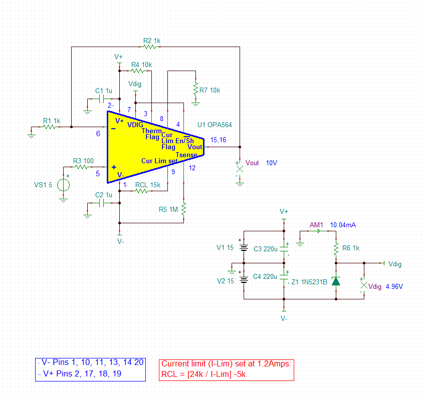
    Actually, simpler is better in this case. The most practical and best approach is to power VDIG from the V+ power supply. Doing so with a simple voltage divider, or a resistor-zener circuit can result in a VDIG source that powers up in near-unison with V+. In Figure 56. Circuits for Generating VDIG, circuit (a) shows a simple series resistor-zener combination connected between V+ and V-. Should you want to apply the resistor-zener circuit here some suggestions: 

    1. Use the lowest capacitance Zener diode that can be identified for the required VDIG level. This will likely be a low power Zener having a rating of 400, or 500 mW, or less.
    2. Use a Zener voltage of 4.7 V, or 5.1 V, instead of 3 V which is at the low end for VDIG. The Zener turns on at a higher voltage and the voltage applied to the VDIG pin will be over 3 V before the charging of the zener capacitance causes the VDIG voltage to slow relative to V+. Doing so keeps the voltage on VDIG coincident with V+ at least until the VDIG circuitry is active internally.
    3. Some possible choices for zeners are the 1N4732A (4.7 V), 1N5231C (5.1 V), BZT52C4V7 (4.7 V), and BZT52C5V1 (5.1 V).
    4. Increasing the available current to the zener diode allows for quicker charging of the diode capacitance. If the circuit can afford 5 mA of current through the zener, then a 8.56 k-ohm resistor would be right for the +24 V/-24 V supplies. Be sure not to exceed the power rating of the zener. Note that the series resistor-zener components could be connected between ground and V- to reduce the power dissipation.
    5. Do not add a capacitor, or minimize any capacitor, connected to the VDIG pin. Capacitance added to the VDIG pin will slow the VDIG voltage rise relative to V+.
    6. Stay away from three-terminal regulator solutions such as that shown in Figure 56 (b). The large capacitances used those circuits can delay the rise of VDIG relative to V+, possibly putting the OPA564 in jeopardy. 

    Your resistive divider approach is a simple, effective solution and introduces less capacitance than the resistor-zener approach. If this has been working reliably with the OPA564 application, there shouldn't  be a reason to change it.

    Regards, Thomas

    Precision Amplifiers Applications Engineering

  • Hi Thomas,

    How is the V e/s control signal implemented prractically ?
    Use of a transistor connected to -12V ?

    Thank you
  • Hi Siauhwa,

    Often, the E/S function is controlled by a digital logic levels that are typical for TLL, CMOS, etc. An input low may be on the order of 0. to 0.8 V, and a high from 2.4 to 5 V, or something similar. The interface between the E/S pin that is referenced to the OPA564 V- level and the positive logic levels can be easily accomplished using an optocoupler, as shown on Pg. 16, Fig. 38. This is mentioned in the Output Shutdown section on Pg. 16.

    There are certainly other interfaces that could be proposed employing bipolar transistors, or power MOSFETs. But the optocoupler provides such an easy, minimal component solution that I don't find a reason to use something else.

    Regards, Thomas

    Precision Amplifiers Applications Engineering

  • Hi Thomas,

    So, for power sequencing, I can just use resistor divider from the -12Vdc. Or I can just use 5.1V zener to +12 and -12V as on the data sheet. Keep the capacitance of the zener as low as possible.

    By doing so, basically it complies power sequences as on fig 36 C....

    Could you please confirm me.

    Thank you

  • Hello Siauhwa,

    Yes, you can power OPA564 VDIG from the resistive divider, or resistor/zener, connected between the V+ and V- supplies. However, since you are using dual supplies the resistive divider, or resistor/zener, can be powered from ground on the high side and V- on the low side as seen below. Doing so will reduce the power used to bias the resistive divider, or resistor/zener. 

    I show an example circuit with the resistor, zener connection. A resistive divider should consume less power because the resistors can be higher in value. Low tolerance resistors (1 %) should be used to accurately set VDIG.

    Regards, Thomas

    Precision Amplifiers Applications Engineering