This thread has been locked.

If you have a related question, please click the "Ask a related question" button in the top right corner. The newly created question will be automatically linked to this question.

INA225: About INA225's internal resister

Part Number: INA225


Hi

I have two questions.

My customers are considering INA 225.

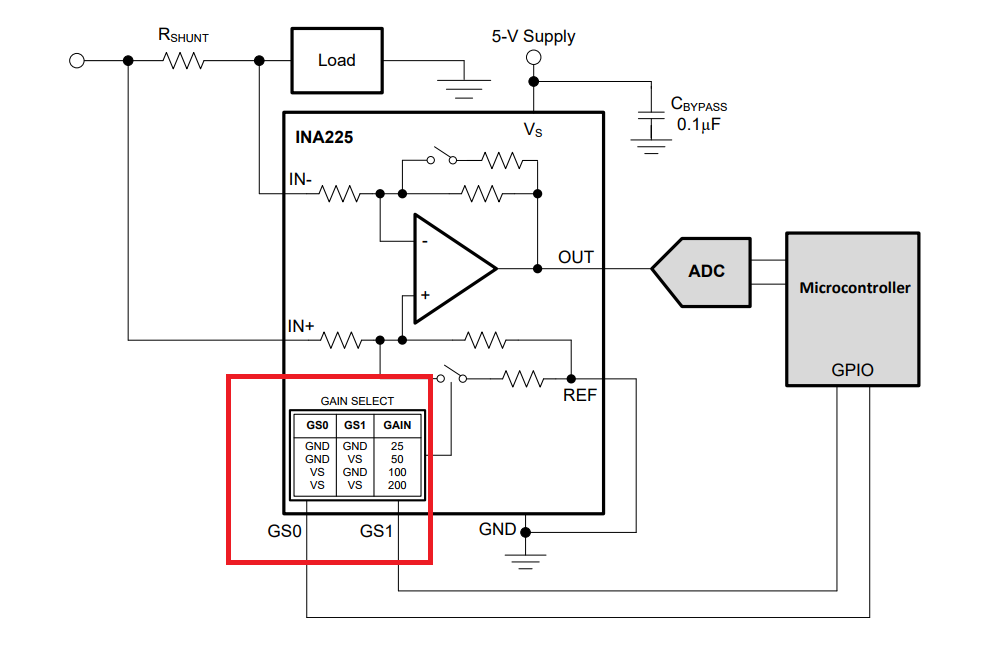
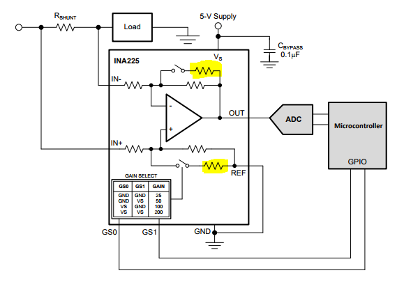
Resistance values of the INA 225 are blank on the data sheet.(For example,figure41)

Please teach me the value of each resistor.

Another E2E'sQA wrote the resistance value as ± 30%, but I would like to know the specific target value.

Also, are there more feedback resistors to determine the gain?

Because the gain combination is four.

As my customers are considering one way detection, customers are considering attaching the attachment data sheet in Figure 41.
When the load current is 0 mA (Vsense = 0 mV), what is the output voltage of each of the four types of gain?

The condition is Vcm = Vs = 24 V.

Best regards,

Ozawa

  • Hi Ozawa,

    Thank you for posting on the E2E forums.
    The diagrams shown actually have no correlation to the part itself, they are only used to exemplify how the device works.
    Normally the internal resistors on silicon do not have an absolute value like those used externally on circuits, they are however matched and trimmed to achieve high levels of precision and low drift over temperature.

    The gain would not be changed by adding or removing resistors externally, not it would be possible to calculate this for multiple parts due to variations in the process.

    Lastly, when the load current is 0mA the output will be equal to the offset voltage. This value is ±75mV nominal, ±150mV Max.
  • Hi Carlos-san

    Thank you for your support.
    Please let me ask another question.

    Which is changing the gain of this device?

    ①Rs resister
    ②Feedback resiter

    Best regards

    Ozawa
  • Hi Ozawa,

    The gain is selected by toggling pins GS0 and GS1 to either VCC or GND as per table below:

    For a same current flowing trough the RS resistor, changing its value will change the output signal, but the gain will remain fixed. 

  • Hello,

    Allow me to cut in.
    It is mentioned on the datasheet P18 as follows.
    Note that there is typically a 525-kΩ impedance (from the combination of the 500-kΩ feedback and 25-kΩ input
    resistors) from each device input to the REF terminal.

    Does the feedback resistor change by gain levels?

    Best Regards,
    Naoki Aoyama
  • Hi Naoki,

    Yes it is part of the gain and feedback system, but not the only one, see diagram below:

    The lower portion is only used to set the offset. The upper portion is what sets the gain. This is done trough switches inside the part, changing the input impedance to the GS0 and GS1 lines would have no direct effect on the gain: They are either accepted as logic 1 or logic 0, as any other digital input.

  • Hi Carlos,

    Thank you for your reply.
    I see.

    The customer want to know the value of the feedback resistor by gain levels.
    Could you tell me the value of the feedback resistor? or could you tell me the
    value of the input resistor?

    Best Regards,
    Naoki Aoyama
  • I've been told the equivalent resistance for each input is about 1.3K, but I don't know how the complete circuit looks like.

    I remind the fact that the diagram in the datasheet is an illustration model rather than what really is inside the part. 

  • Hi Carlos,

    Thank you for your reply.
    I'll feedback the customer this information.

    Very Thanks,
    Naoki Aoyama