This thread has been locked.

If you have a related question, please click the "Ask a related question" button in the top right corner. The newly created question will be automatically linked to this question.

Overshoot with LMH6401 with in/out transformers, step signal input

Other Parts Discussed in Thread: LMH6401, TINA-TI

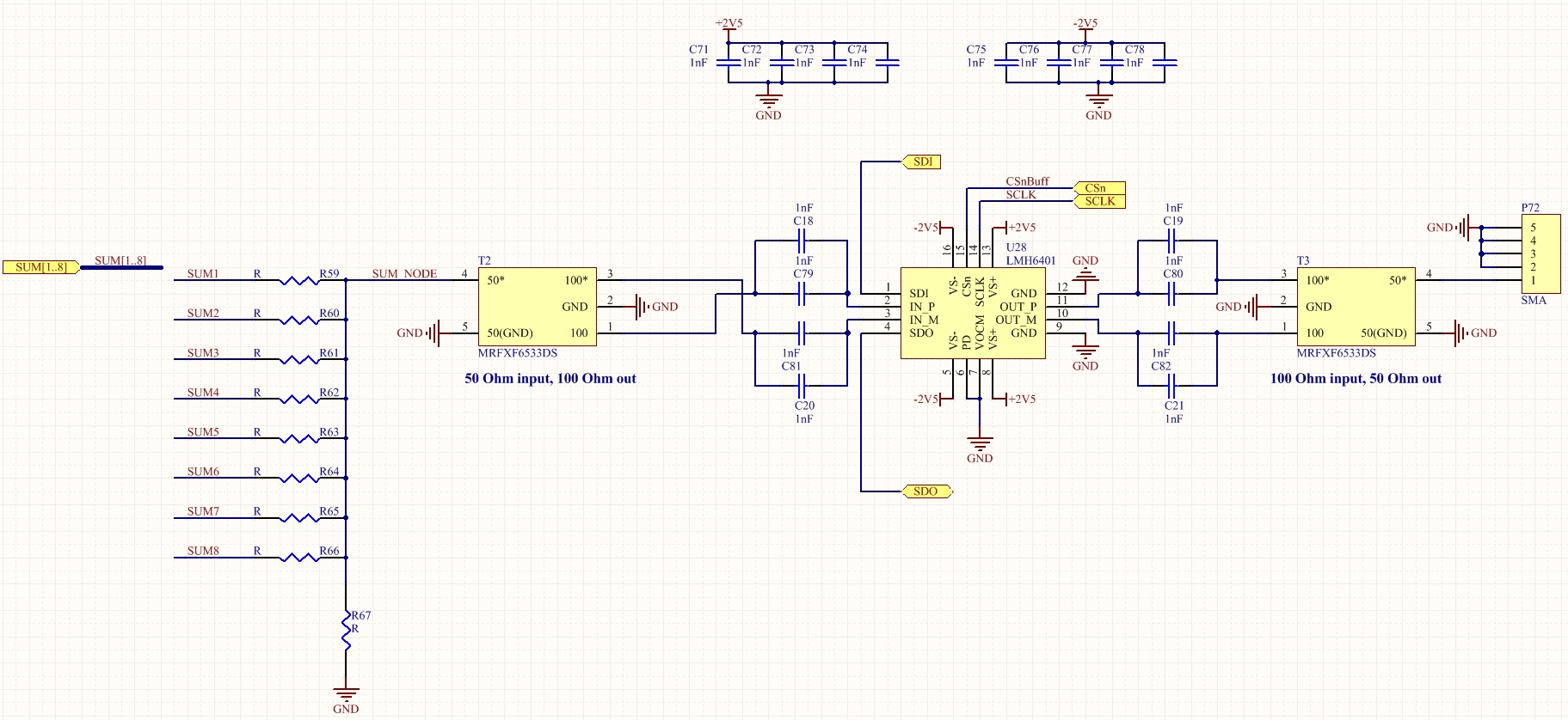
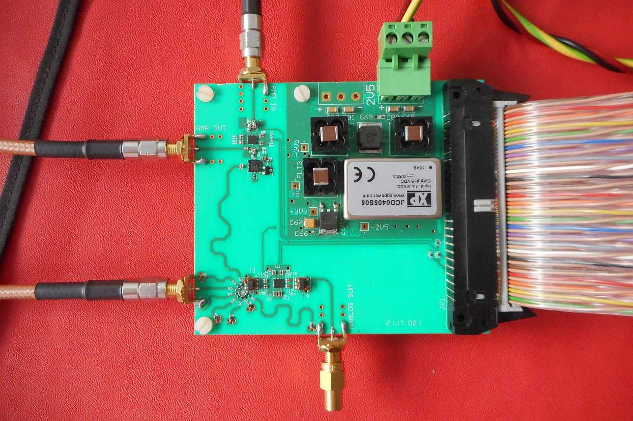
The schematic is below.

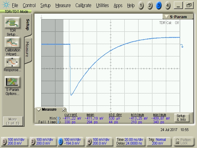
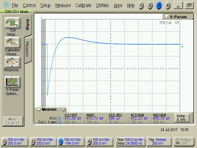
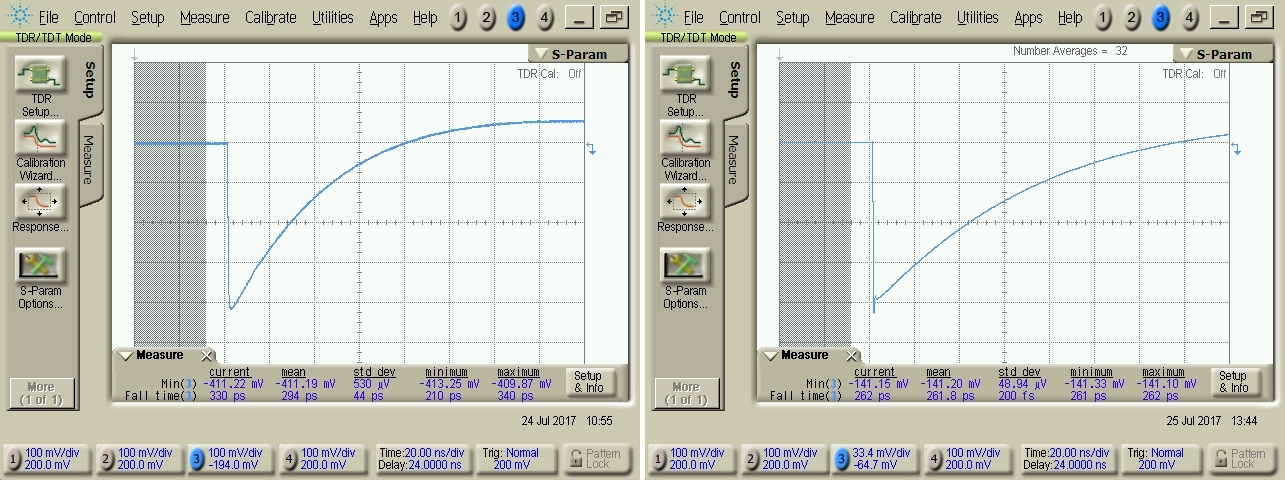
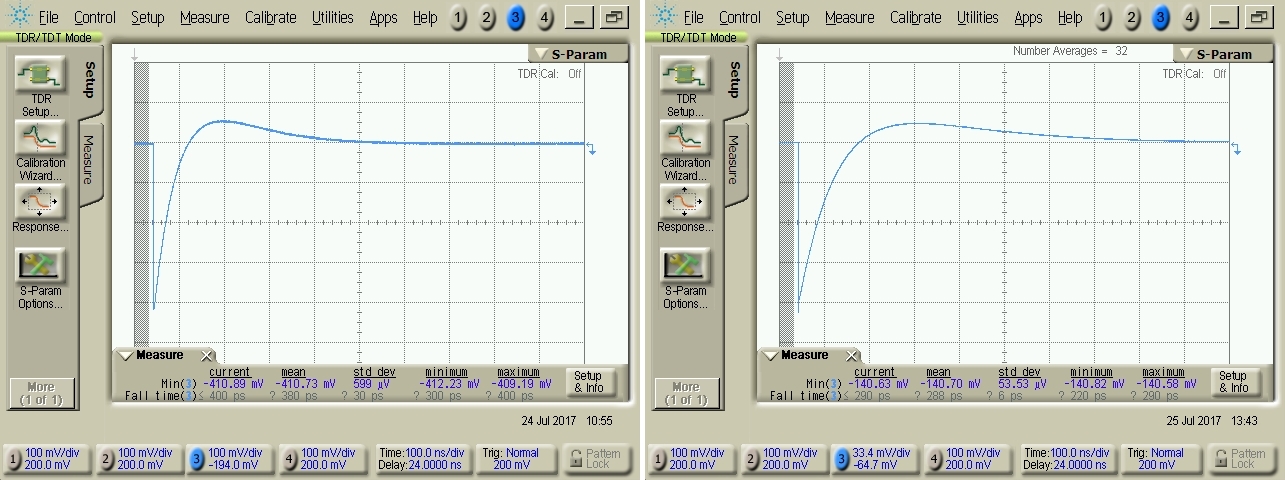
I apply a step pulse in one of SUM inputs with a TimeDomainReflectometer, step risetime is about 20 ps, and on outptut I see a big overshoot.

Questions:

- why?

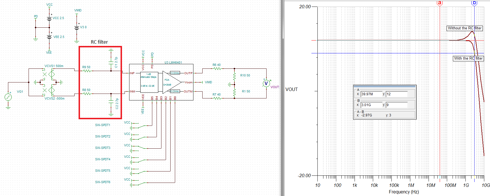
- could be eliminated?

- in the final application the step input will have a risetime of about 1ns: could it mitigate the overshoot?

Thanks

   Fabio


  • But ... I've included three screenshots, where are?
  • Hi Fabio,

    To answer your questions:

    1. A primary reason to notice overshoot in the step pulse is if there is any peaking in the frequency response of the device. The LMH6401 has ~2.5dB of peaking which could be the reason as to why you are seeing an over-shoot in the pulse response. Another reason is that you seem to have improper termination at the LMH6401 device inputs and outputs. Looking at your schematic, the LMH6401 input is 100-ohms differential whereas the input Tx- balun presents a 200-ohm source input, which could cause over-shoot due to source and load mismatch. Also, the LMH6401 outputs are directly connected to the output Tx-balun without a series output resistor. I would recommend at-least 20-ohm series resistor from each output to the Tx-balun for eliminating any sources of over-shoot. Lastly, the 20ps rise time pulse is too fast and would require a 17.5GHz amplifier to properly settle without exhibiting any overshoot. So, slowing the rise-time of the pulse would help.

    An easy method to fix the over-shoot is by incorporating an RC filter at the LMH6401 input, which should take care of the 2.5dB peaking in the frequency response as well as the input source and load mismatch. A TINA-TI circuit is attached below showing the comparison between the frequency response of with and without the input RC filter. 

    LMH6401_InputRCfilter.TSC


    2. Yes, it is possible to eliminate the overshoot. The method is described in the above answer 1.

    3. Yes, it is possible that making the step rise time to 1nsec would not significantly exhibit the overshoot. However, If you are concerned about over-shoot, I would highly recommend you to incorporate the RC filter at the LMH6401 input as shown in answer 1.

    Best Regards,

    Rohit 

  • Hi Rohit, thanks a lot for your analisys.

    I've implemented the input filter and added the output series resistors, now the overshoot is more or less disappeared.

    Just a note to try to optimize the solutions:

    the rf transformer windings and ratio are:

    so the impedance seen at the balanced output should be 100 Ohms if at the input there are 50 Ohms.

    In my circuit the resistive input netwrok impedance at SUM_NODE is about 10 Ohms.

    Is the input filter 50 Ohm/2.7pF the optimum or we can do some valuea adjustement to have

    the same overshoot reduction and some losses reduction?

    Thanks again

      Fabio

  • ... mmm ... disappeared in the displayed time window, but it has been delayed as you

    can see here, on the left before the filter and on the right after the filter implementation, only a small reduction

    Here a picture of the testboard, the circuit is on the bottom, you can see the two transformers.

    Input step comes from the left-bottom, output on the bottom:

    How to proceed?

    Thanks

      Fabio

  • Hi Fabio,

    It is possible to adjust or optimize the RC input filter of 50-ohms/2.7pF in-order to get the optimum over-shoot and loss reduction. I think the right value of RC input filter will need some playing around given your setup includes the input/output transformer. If you have the S-parameter models of the input and output transformer, then I think you should be able to simulate the signal chain response in ADS and try to understand from where the over-shoot is coming from.

    The other thing I noticed is that the time scale on the x-axis for the zoomed out TDR capture is 100nsec/div. If the overshoot settling is that long then it probably points to the longer term settling due to thermal tail issue present in all SiGe devices built in silicon-on-insulator (SOI) technology. The thermal tail and correction is extensively documented in Section 10.1.3 of the LMH6401 datasheet. You should be able to play around with the thermal feedback control registers of the LMH6401 device in-order to try and correct the thermal tail or long-term settling. How much overshoot (in % or mV) from the nominal value (is it 410mV ?) are you recording at the LMH6401 output?

    One last thing is that I would avoid using series ac-coupling capacitors for pulse-domain measurement because it really blocks the DC content of the pulse and results in long term settling. It looks like you are operating the LMH6401 on +/-2.5V supply, so you probably don't need the 1uF cap at the input and output.

    Best Regards,
    Rohit
  • Hi Rohit.

    The overshoot is about 12%, 0.5 div/4.2 div.

    I'll give a look to S-parameters ...

    I've already implemented the thermal compensation programming using the datasheet example values of GAIN=10 and FREQUENCY=9 but I can see only a

    small change in amplitude signals, less than 1%.

    About the AC coupling with 2x 1nF capacitors, it is because the power supply is provided by an external variable power supply that provides not

    extactly 2.5V, but there are 10-20 mV of differences. Anyway I'll try with DC coupling on the input, on the output is not possible.

    Thanks again.

      Fabio

  • Just a few words about the thermal compensation.

    My control system programs the gains correctly, all gains, and I've checked with an oscilloscope the SPI activity

    when I set the gains, the thermal gain and frequency compensations, and all seems to me correct.

    I see the register address to be 2 for the gain, 4 for the thermal gain and 5 for the thermal frequency compensation.

    I see the 8+8 SCLK pulses for address+data, MSBit to LSBbit, right CS, good setup and hold times.

    The SPI writing routine is one only, it is called with different address and data parameters for the three registers.

    I believe it is correct. Why I don't see good effects when I play with thermal compensation? Really, I don't know.

    F.

  • Hi Fabio,

    The thermal compensation only provides compensation for about 1% of the amplitude change, as you have noted.

    I would recommend you to instead play around with the RC filter, probably increase the C to 4.5 or 5.6pF keeping the R as 50-ohms, in-order to see the difference in overshoot response. Have you also tried to measure the pulse response with 1nsec rise-time to make sure there is less over-shoot?

    Best Regards,

    Rohit

  • Hi Rohit.

    The overshoot problem was in the AC-coupled scheme, I have reproduced it in simulation.

    So, now I run in DC-coupling mode between all stages (my circuit has two LMH6401 stages) and the

    overshoot is disappeared.

    Using a 2ns risetime step which inject some charge through a 150pF capacitor to the 16 channels I have in my board,

    now I can see very good signals at the output of final amplifier which is the subject of this thread.

    What I need to know now is the input-to-output transit time of LMH6401, min/max values, this is to evaluate

    the skew between the 16 channels, what could be for LMH6401, what for a SPDT integrated switch and

    what for striplines mismatches.

    Please let me now Rohit,

    thanks again

  • Hi Fabio,

    The nominal transit-time from input-to-output of LMH6401 could be ~120psec across gain settings. I have attached a plot of group delay vs frequency for maximum gain below which should give an idea about the input-to-output transit time of the LMH6401.

    Best Regards,

    Rohit

  • Thanks a lot Rohit.

    Do you know the group delay min/max as it randomly change fron a component to another?

    In my board I have 8 LMH6401 followed by 8 (1/each) integrated GHz SPDT and I have a time

    skew between the 8 channels of 500 ps worst case.

    I have to know how much is from SPDT, LMH6401, microstrips.

    Can you give me the above min/max values?

    Anyway I'll go to measure the signals on their path.

    Thanks

      Fabio