This thread has been locked.

If you have a related question, please click the "Ask a related question" button in the top right corner. The newly created question will be automatically linked to this question.

XTR300EVM: Output waveform has spike on it leading edge

Part Number: XTR300EVM
Other Parts Discussed in Thread: XTR300

I am testing the XTR300 voltage to current amplifier for possible use in application where a +- 10V signal will be converted to a +- 20mA signal that will be driven through a 100-1000 Ohm load.  The signal will be modulated at approximately 1KHz.  I am using the XTR300EVM for the test.  I removed the 2.5K Ohm  "RSET" resistor and installed a 5K Ohm resistor in its place.  I am using a 100 Ohm resistor for the load. I am driving the input with a +-5 V square wave at 1KHz.  I have attached a picture of the setup as well as a picture of the oscilloscope attached to the input and load.  There is a terrible spike on the leading edge of the output wave  
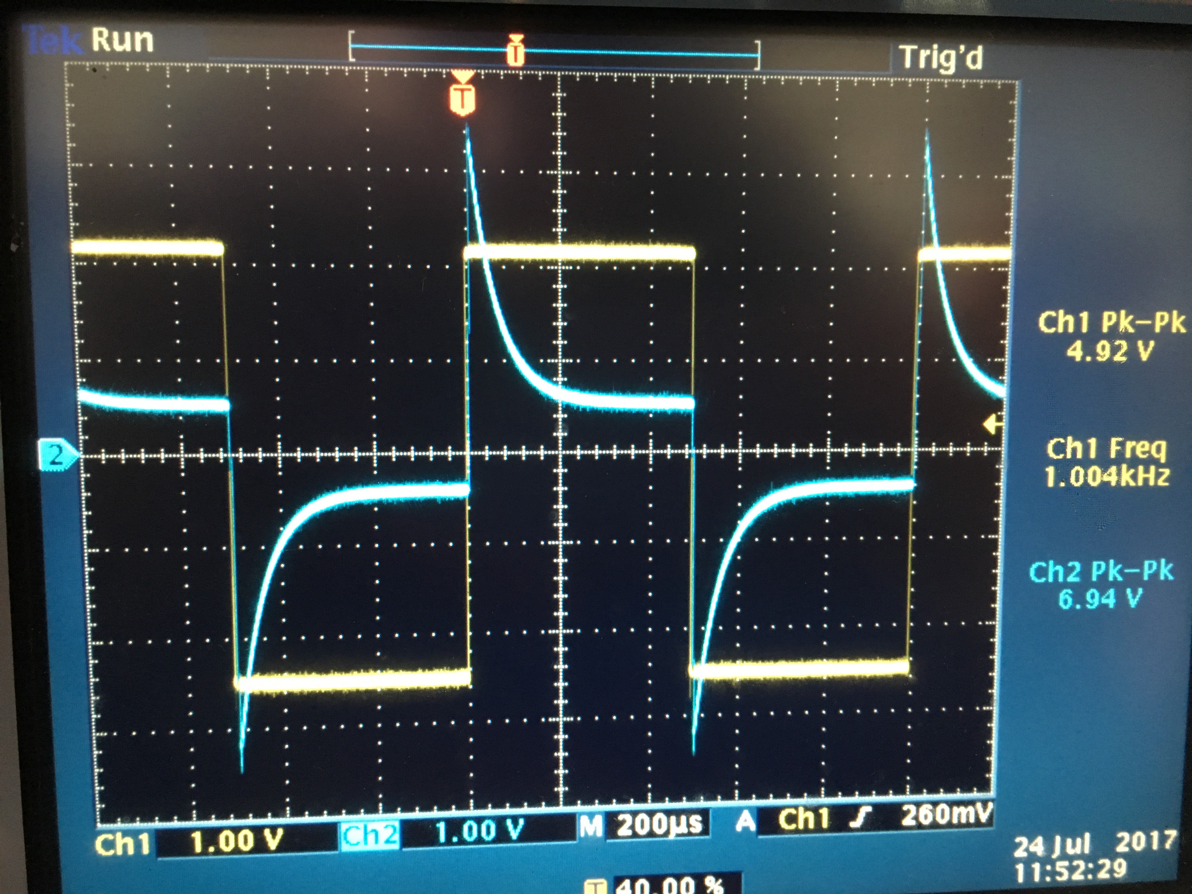
form.  Is there something wrong with my setup?  If not, then is there way to get rid of the spike?  Is this the wrong device for this application?  Is there something that would work better? 

  • Hi Kevin,

    What you are seeing is related to the compensation of the XTR300. A useful parallel to understand what is going on is to think of compensating a 10:1 scope probe. Here is a useful link regarding this procedure if you are unfamiliar:

    What you have now is an under-damped system. One way to look at this is through the RC time constants (tau) of your load and feedback components. For your case, the tau of your feedback is significantly larger than the tau of your load. This means the low pass filter cutoff frequency of your feedback network is significantly lower than the load filter, and so your feedback network is not able to respond as quickly to transients, so you see overshoot before the output regulates to the expected level. If the opposite were true and your feedback network had a higher cutoff frequency, you would see an over-damped response. Ideally, you want these cutoff frequencies to be as close to each other as possible to achieve a critically damped response. For your application, I would suggest trying a 1nF feedback capacitor  (C3 on the EVM) and see if this looks satisfactory for your two load extremes.

    Regards,

    Zak Kaye