Other Parts Discussed in Thread: OPA2140, THS4541, TINA-TI
I am troubleshooting a circuit with the THS4131. It is a new version of an old design where the THS4131 is also used and whose performance is OK. The problem is the original designer used high value resistors, 47kOhms and 4.99kOhms (so gain ~9.4) on the feedback network. I know, these values are way higher than the prescribed by the data sheet. However, in our design the THS4131 is used for its differential feature and its low noise, not its high speed (it amplifies an amplitude modulated 125kHz sinewave), so bear with me.
The circuit before the differential amp is the same as the original design, the main change is the ADC it feeds. However, we are finding a higher noise with this new design. We are trying to locate the source of noise and, so far, the AD has been discarded (its performance meets the expectes from data sheet). We then connected the differential amp and short-circuited its inputs the the common mode node of the AD (actually, to the voltage follower of it - an OPA2140).
We performed a data capture with a couple thousands samples and ran an FFT and we noticed a 1/f like response that extends through around 300kHz. This noise is the reason for this post because as per the data sheet both input voltage and current equivalent noise has a knee around 1kHz and we are seeing it happen around 300kHz. What could cause this 1/f (kind of) noise? At 125kHz the noise level is much higher than on the flat noise range (some 4 to 6 times) thus demodulating it results in higher output noise, making the circuit unsuitable for the application.
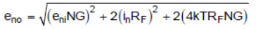
FWIW I have done a noise estimation of the circuit based on an article by Michael Steffes in EDN as well as the section 8.5 of THS4541 data sheet cited there. I did not consider the 1/f noise because of the knee at 1kHz that is not relevant for my application and considered a bandwidth of 2.5kHz due to the demodulation. The resulting noise is lower than what we are observing on the FFT and, anyway, it was supposed to be flat on the range considered.
So the question is could the use of higher value resistors be the cause of this 1/f behavior? Or there could be another cause I am missing?
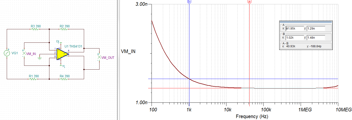
Also, could the THS4131 be used with higher value resistors than the 390R in the data sheet, say, Rg=1k, Rf=10k-ish? I would not like to use low values because power consumption and heat sinking are critical in this design.
FWIW the sampling rate is 5MSPS, FFT buffer size is 2000 18-bit samples.
Thank you all in advance for any hint.