This thread has been locked.

If you have a related question, please click the "Ask a related question" button in the top right corner. The newly created question will be automatically linked to this question.

INA129: INA129 for bio signal application

Part Number: INA129
Other Parts Discussed in Thread: INA128

Hi,

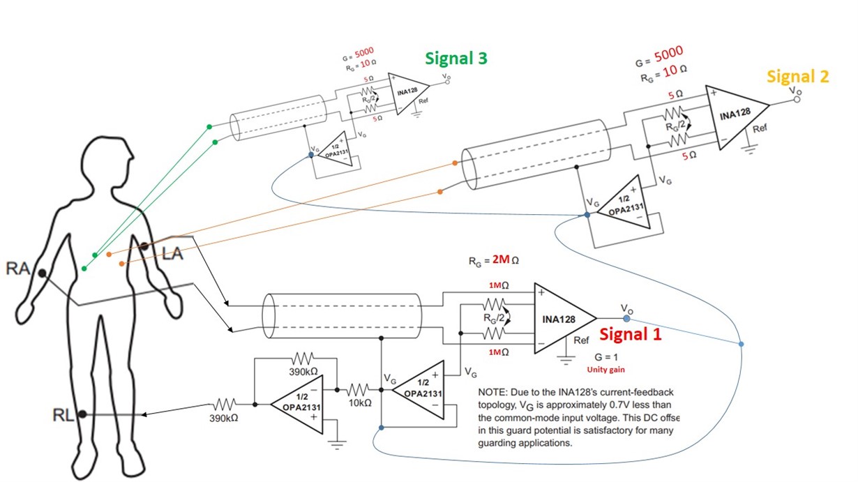
Referring to the attached schematic, I've slightly modified example application of INA129 and was wondering whether what I'm trying to achieve here makes sense, and if it is the best way to do this? 

My main signal of interest is the diaphragm muscle which sits right underneath the heart, this muscle has a signal amplitude in micro Volts range, compared to the heart that is in mili Volts range. Signal 1, acquires the heart muscle signal as suggested in INA129 datasheet, except that I've set the gain high enough to achieve unity gain/not amplify it, then it is fed into the same right leg driver, hoping to remove this common 'noise' from signal 1 and signal 2? then signal 1 and 2 are amplified by x5K gain to increase the resolution before digitization. Am I on the right track?

Also what is the purpose of that 10k resister in right leg drive circuit before inversion? Thank youu in advanceee!    
  • Keivan,

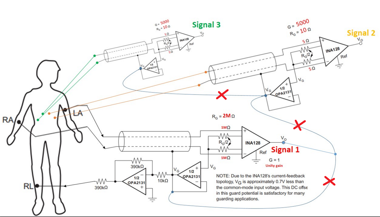
    Using two 1M resistors instead of 2.8k shown in INA128 datasheet sets the gain of INA128 to G=1.025, and thus as you said minimizes amplification of the signal1, but this is a wrong signal since INA128 amplifies differential and not common-mode signal.  The reason for using common-mode signal, VG, is to drive it after inversion back into the patient through the right leg, RL, in order to cancel 50/60Hz common-mode signal coming from the power grid.  Placing INA128 in low gain will result in Signal1 being close to Vref (GND) instead of VG, and thus driving RL with such signal is NOT what you want and thus you need to remove this connection.

    Also, there is only one common-mode signal that you need to use for power grid noise cancellation and thus there is no need to triple it up (I will not go here into all the reasons why you may NOT attempt to sum multiple voltages by simply shorting them).  For those reasons, please remove all three connections as shown below.  As far as your question about the reason for 10k resistor, it is part of the inverted gain: G = -(390k/10k) = -39 while 390k at the output is just there to limit the output current delivered to right leg.  For more info, please read attached ECG/EEG Application Reference Guide. 


    ECG an EEG Applications.pdf