This thread has been locked.

If you have a related question, please click the "Ask a related question" button in the top right corner. The newly created question will be automatically linked to this question.

Looking for a precision amp to build a unity gain buffer for low frequency piezoelectric hydrophone

Other Parts Discussed in Thread: OPA191, OPA376, INA110, INA163

I am getting lost in your plethora of OP-Amps.  I am looking for product suggestions for a very specific application.  This system serves as the primary calibration for hydrophone standards.  I need to design a precision unity gain buffer amplifier to interface a hydrophone to a true RMS voltmeter.  The input is a direct connection to an un-grounded piezoelectric sphere operating as a balanced charge source across a 4 nF capacitance.  The output will drive the single ended 10M ohm input impedance of a Keithley 2000 DMM.  The voltage span is 1 mVrms to 300 mVrms, over a frequency span of 1 Hz to 4 kHz.  The preferred configuration is to connect the buffer amplifier directly to the BNC connector of the transducer, which is connected directly to the ceramic through 1.5" of wire.  The alternate configuration would be to connect the transducer to the buffer with 1m of balanced shielded cable.

  • Hi Greg,

    we will try to help you finding a fitting part.
    You have already given a detailed description about your project which is very helpful for us.
    Still, can you share a schematic showing the described connections? Which power supply is available?

    Regards,
    Miriam
  • Thanks for responding.  Here is a simplified schematic.  I can provide single or dual supply voltages up to +/- 24V.  The purpose of the buffer is to adapt the balanced voltage on the ceramic sphere to the ground referenced input of the DMM without modifying the signal.  The actual signal is a sine wave voltage that varies from 1 mV to 200 mV RMS over a frequency span of 1 Hz to 4 kHz.  I would prefer to implement the buffer using surface mount components in a small Pomona style box with integral BNC connector so that the buffer amp may be connected directly to the BNC jack on the hydrophone case.  This same amp will be moved back and forth between complementary reciprocal hydrophones during the measurement process.  The final calculations are dependent upon the relative voltage outputs of the two hydrophones, so it doesn't matter if the gain is not exactly unity (A=1), as long as it is stable and consistent.

    Best Regards,

    Greg Blasdell

    Underwater Sound Reference Division

    NUWC Division, Newport

  • I guess the schematic didn't come through. I can e-mail a pdf.

    Greg
  • Hi Greg,

    did you use rich formatting and the attach-tool? Drag and drop often doesn't work.

    Best,
    Miriam
  • Simple Buffer Amp.pdf

    Ok, I tried the 'Insert'.  This is my first time using this.  The attached is a pdf file.

    Greg

  • Hi Greg,
    thanks for sharing. I have some final questions. What is important in your measurement: low bias current, low offset (e.g. 800uV or way lower), low noise? Do you know the value of the resistor/impedance in the hydrophones?
    Regards,
    Miriam
  • Miriam,

    The hydrophone consists of just the raw PZT sphere inside a rubber boot filled with DB Castor Oil.  When measured with an HP 4192 impedance analyzer it presents a pure capacitance with a dissipation of 0.001.  The conductance reading gives an out of range indication, so we are looking at an equivalent shunt resistance well into the tens of gigaohms range.

    The buffer amplifier needs to have the lowest self-noise possible.  I am looking for an input offset voltage of 10 uV or less, and input bias currents no greater than 50 pA..  Our current device for measuring the drive current of the acoustic projector uses a device with input bias currents specified at less than 15 pA.

    The key function of the buffer is to read the output of hydrophone A exposed to a specific acoustic pressure, then switch it over to an identical hydrophone B exposed to the same acoustic pressure.  The calibrations are dependent upon being able to accurately measure a difference between the two hydrophone output voltages as small as 100uV over a range of 1 Hz to 4 kHz.  I know that this is a tall order, but I am hoping that the newest integrated operational amplifier designs are up to the task.

    Regards,

    Greg

  • Hi Greg,

    do you want the output to be centered around zero? If so, you should use a dual supply for the buffer. Is the hydrophone referenced to ground or to a reference voltage? The reference voltage shifts the common mode at the buffer amp.

    Based on your information I can recommend using the OPA191 or OPA376.

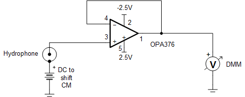
    The OPA376 has a typical offset of 5uV and a maximum input bias current of 10pA. The max supply voltage is 5V though, i.e. either the available 24V has to be attenuated or you might already have this voltage available.  If the output signal should be centered at zero, you should apply +/- 2.5V. If you use a single supply, you should reference to e.g. 2.5V at the input at a 5V supply to ensure that the output is not clipping.

    I attached an example with the OPA376.

    The supply voltage at the OPA191 is max 36V which suits your available supply. But again, make sure that the output is not clipping with a correct reference at the input.

    Consider to limit the bandwidth of the buffer with an output filter to limit the noise. Does it depend on the human hearing (20-20kHz)? The best is to add a decade to the frequency that is filtered, for human hearing e.g. the filter cuts off at 200kHz accordingly.

    If the input offset voltage is not as important as you first considered, you can also use an INA with a low input bias current. It seems for me that it is only important to compare the hydrophones and the result should not be influenced if they have the same offset.

    Hope this helps,

    Miriam

  • Thanks Miriam.

    The hydrophone source voltage is not ground referenced.  It is an unreferenced, balanced RMS voltage across the 4 nF capacitance.  Therefore, I assume that some form of balanced bias resistor circuit will be required on the differential input.  The frequency range is strictly 1 Hz to 4 kHz, so it is in the mid-sonic to sub-sonic region.  We can use a maximally flat low pass filter with a cutoff well below 20 kHz.

    I can produce any bipolar supply voltages up to +/- 50 Vdc.

    Greg 

  • Hi Greg,

    you are right with the bias resistor. Considering that the input offset voltage is less important than expected when the input and output is AC-coupled, you can use the INA110 which has a max input bias current of 50pA but a higher input offset voltage of max 250uV. An FDA is advantageous for your application since the inputs are differential.
    An application example for AC-coupling and biasing is given in the datasheet of the INA163 Figure 5 for a Phantom-Powered Microphone Preamplifier.
    Is that feasible for your application?

    Best,
    Miriam
  • Hi Greg,
    I hope you were able to solve your issue.
    If you have questions or need further support, please reach out.
    Best,
    Miriam