This thread has been locked.

If you have a related question, please click the "Ask a related question" button in the top right corner. The newly created question will be automatically linked to this question.

XTR111: XTR111 - current limit -

Part Number: XTR111

Hi,

I have some problems to understand the device and the neccesary short circuit protection, the function of the external short circuit is no problem.

I thought that the device will limit the output current as a function of Vin.

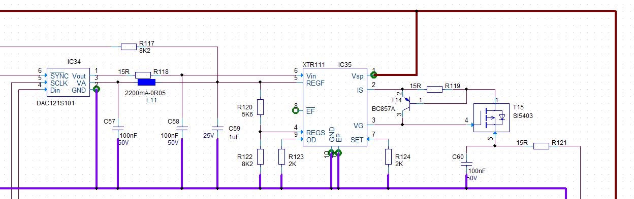
So for example If I have Vin = 2V, Rset = 2K I will get an output current of 10mA, independent of the load.

If I have a load of 1Ohm , the outout current should be still 10mA. So why do I have to limit the output current ?

Kind regards

  • Hello Christoph,

    Your example is correct, IOUT=10(VVIN/RSET).  10mA=10(2V/2kohm).  

    However, to help you, we will need some more information on the application.   Can you provide a snip of your circuit schematic?  What are your power rails?  

    Current sources are limited by their compliance voltage limit which is the maximum voltage they can supply.  For the XTR111, it has a compliance voltage limit of 2V below the positive power supply.  Knowing your circuit configuration and supply rails will show what your compliance voltage is.  In your case, if the output current times the load resistance is greater than approximately the compliance voltage limit of 2V , the current will not be properly regulated.

    I look forward to your reply

    Best regards,

    raphael

  • Hello Raphael,

    thanks for your explanation.

    If I understand you, the voltage at the external fet will be regulated to limit the current, that is the function of the "I-Mirror" in the block diagram.

    Attached you will find our schematic, our supply voltage will be 10V and the output current shall be in the range 0mA< Iout < 20mA and we allow an external load between 1Ohm - 400Ohm.

    Regards,

    Christoph

  • Hi Christoph,

    I believe your understanding is correct. The addition of the PNP transistor and 15 Ohm resistor limits the gate-to-source voltage of the FET once sufficient current flows through R119 to turn on T14. This keeps the FET from entering a low impedance state and pulling excessive current. However, for this to function properly, you need to make sure the limiter is placed between the gate and the source of the FET. In your schematic it looks like you may have the source and drain connections flipped.

    As Raphael mentioned, the XTR111 has a compliance voltage that extends to 2V below the positive rail. On a 10V supply this means you cannot exceed 8V at the load. With a 400Ohm load at 20mA you are operating right at this limit, and this is not factoring in any voltage drops that may occur across cabling or other components in your loop. To be safe, I would recommend increasing your supply voltage, otherwise the XTR may struggle to regulate with a 400Ohm load.
  • Thanks a lot !

    Regards,
    Christoph