Dear,
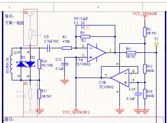
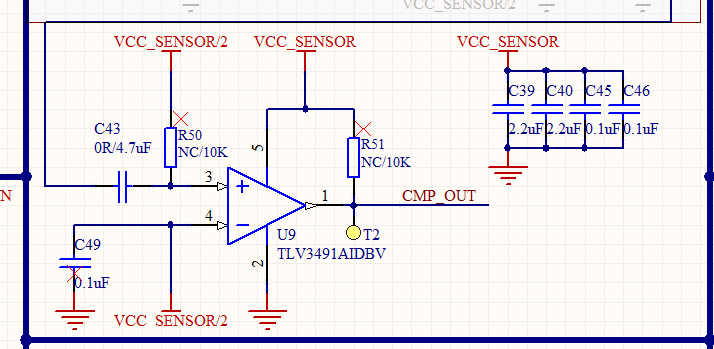
Our customer use the channel B of TLV8802 as voltage follower, the OUT B is connected to +IN A as DC bias, and to IN- of comparator, the voltage of V+ is 3.6V. When +IN B is applied to 1.8V through divider resistance, the waveform of OUT B should be steady at 1.8V level. However, the waveform of OUT B has self-oscillation of about 2K frequency, 50~80mV amplitude. So they removed C11 (0.1uF) connected to OUT B, but it does not improve. Then they remove C49 (0.1uF) connected to OUT B, the waveform seemed to no longer be self-oscillation obviously.
So, why two 0.1uF capacitor cause self-oscillation at the output of follower? How do we avoid the self-oscillation? And what the formula to calculate the frequency and the amplitude of self-oscillation waveform? Thanks a lot!
Customer's SCH as follows (red"x" mark means no soldering):


