Because of the Thanksgiving holiday in the U.S., TI E2E™ design support forum responses may be delayed from November 25 through December 2. Thank you for your patience.

This thread has been locked.

If you have a related question, please click the "Ask a related question" button in the top right corner. The newly created question will be automatically linked to this question.

TLV8802: The self-oscillation problem of follower's output

Part Number: TLV8802

Dear,

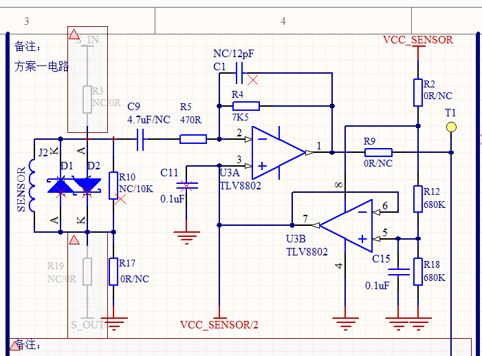
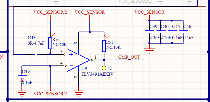
Our customer use the channel B of TLV8802 as voltage follower, the OUT B is connected to +IN A as DC bias, and to IN- of comparator, the voltage of V+ is 3.6V. When +IN B is applied to 1.8V through divider resistance, the waveform of OUT B should be steady at 1.8V level. However, the waveform of OUT B has self-oscillation of about 2K frequency, 50~80mV amplitude. So they removed C11 (0.1uF) connected to OUT B, but it does not improve. Then they remove C49 (0.1uF) connected to OUT B, the waveform seemed to no longer be self-oscillation obviously.

So, why two 0.1uF capacitor cause self-oscillation at the output of follower? How do we avoid the self-oscillation? And what the formula to calculate the frequency and the amplitude of self-oscillation waveform? Thanks a lot!

Customer's SCH as follows (red"x" mark means no soldering):

  • Hello Shaw,

    As a general rule, you cannot place a capacitor directly on the output of a op-amp. Most op-amps will start to ring or oscillate with as little as 50pF. Followers are the most unstable configuration.

    The TLV8802 is a nanoppower amplifier, and is even more sensitive to capacitive loading. 0.2uF is way too much load. For the circuit shown, removing C11 and C49 should stop the oscillation.

    Normally a resistor is placed between the output and the load capacitance. For the nanopower TLV8802, the series resistor may need to be as large as 20k-50k.

    Please see the TI Precision Labs videos and materials on Stability for more information and solutions.

    Again, because the 8802 is a nanopower device, it cannot drive much current. 100K is a heavy load. You may need to increase the feedback resistor values (R4, R5). It also looks like you do not have a DC bias path for the comparator input if R50 is not populated. R50 should be fairly large, such as 1M (scale C43 appropriately).