This thread has been locked.

If you have a related question, please click the "Ask a related question" button in the top right corner. The newly created question will be automatically linked to this question.

Charge amplifier with low impedance input

Other Parts Discussed in Thread: OPA337, OPA191, TINA-TI, OPA140

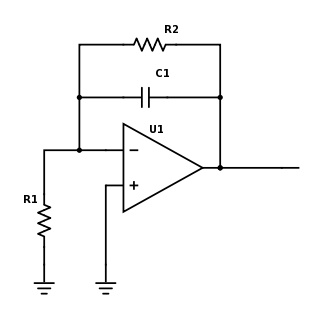
Hello, I am looking for help designing a charge amplifier that has very low input impedance.  My basic circuit design looks like this:

Here, R1 is a many-turn coil (200-100 turns, depending on the wire gauge) about 8 inches in diameter with resistance from 3 ohm to 130 ohm.  In this application, I am changing the magnetic field near the coil, which then generates a current in the coil.  I want to integrate that current to find the total charge that flows in the coil.  I expect around 0.5 to 3 nC.  However, the magnetic field takes about 1 s to change, so I have been using C1 = 30 nF and R2 = 30 Mohm.  That combination of R1 and R2 produces a lot of noise when there is no signal in the coil.  Is there a good amplifier that will work for my application?

  • Hi Matthew,

    Op amps have very high input impedance and low output impedance. This low output impedance is what you need to measure the whole charge running through the coil.

    I need more information to understand your application. You're talking about a coil and it sounds like you're using a transformer. Do you have a more detailed schematic?

    There is an example of a Charge Amplifier in our Analog Applications Journal:

    Does Figure 6 describe your application?

    The noise you see is caused by the high feedback resistor. The article describes on page 26 the correlation between the thermal noise and the feedback resistor. Thus, it is better to choose the feedback resistor as low as possible.

    Furthermore, a low R1 and a large R2 cause a very high gain and probably cause the op amp to swing against the rail.

    I can help you finding a fitting amplifier and configuration. Therefore I need to know the gain, supply voltage, frequency and desired output range. Do you need a rail-to-rail part?

    The more information you share, the better I can help you.


    Best,

    Miriam

  • Hi Miriam,

    Thanks for the reply.  The circuit in Fig. 6 is much more complicated than my application.  The coil is not a transformer, it really is just a coil, hand-wound around a spool.  The spool is 8 inches in diameter, and the coil has between 200-1000 turns.  So the coil has a very low inductance and very low capacitance, and really is best described as a resistor.  But the coil has such a large area it is sensitive to small magnetic field changes.

    I don't have a more detailed schematic -- what I posted really is what I am trying to use.

    I know the noise is caused by the high feedback resistor, but if I lower the feedback resistor, I also drop the RC time constant of the charge amplifier.  My system has such a low frequency it is essentially DC, so I want to keep the time constant low.  Right now, the magnetic field takes about a second to change, and I want to measure the total current that flows over that one second.  So my frequency is 1 Hz or less.

    Keeping the op amp from swinging to the rails is quite hard, that is for sure.  It only seems to work when I have an op amp with an internal offset trim.

    I am using a +/- 15 V supply.  Ideally, I would turn 1 nC of charge into 1 V, but that would require the feedback resistor to be 1 nF, which drops the time constant to be quite low.

    Would there be a better way than a charge amplifier to measure the total current that flows through this low resistance coil?

  • Matthew,

    OPA337 is a low voltage amplifier with the maximum supply voltage of +/-2.75V so you may not power it using +/-15V supplies.

    You cannot pick the value of the feedback resistor based solely on the desired RC time constant because as Miriam mentioned using too large R2 will drive the output to one of the rails.  130 ohm input resistor together with 30Mohm feedback resistor creates a gain of  230,769 which will attempt to amplify  OPA337 maximum input offset voltage of +/-3mV to +/-693V while 3 ohm R1 creates a gain of 10,000,000 that will attempt drive the output to maximum of +/-30,000V, which of course will result in the output saturating against one of the rails.

    Also, any coil has an inductance but all you say is that it has 3 to 130 ohm resistance and you don't show or mention what its inductance may be?  If the input resistor, R1, is actually a coil with some series resistor, you need to show it as an inductor in series with a resistor and provide an estimate for its inductance.

    All in all,  if you want to use a large feedback resistor, you need to pick an op amp with lowest possible input offset voltage - one such high voltage op amp is OPA191 with the max offset voltage of +/-25uV and the max supplies of  +/-18V.  If you use +/-15V supplies and R1 of 3 ohmit, in order to avoid driving the output to one of its rails, this would allow you to use max R2 of 1.8M or less:  +/-25uV* 1.8M/3ohm =+/-15V.

  • Hi Matthew,

    thanks for the reply.

    As Marek said, using such a high feedback resistor will result in a very high gain as soon as R1 will be small. The high range of the coil resistance makes it difficult to find a part that won't saturate in the charge amplifier configuration. Therefore you have to consider reducing the feedback resistor and increasing the feedback capacitor. What made you choose C1 = 30 nF?

    Can you describe the purpose of the application more detailed? Do you want to indirectly measure the magnetic field? Do you have control of the magnetic field and know the magnitude of the induced current? What is the range of the current?  This information can help to find another configuration to measure the current.


    Best,

    Miriam

  • Hi Marek,

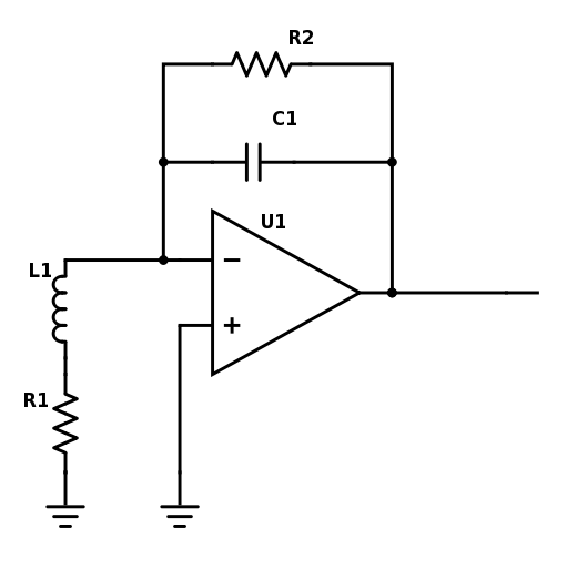
    Thanks for the reply.  You are right the coil in the input does have some inductance and so is better modeled as an inductor and resistor in series.  The circuit would be:

    I measured my coil inductance to be 446 mH (R1 = 130 ohm) for the 1000-turn coil and 8.6 mH (R1 = 3 ohm)  for the 100-turn coil (28 gauge wire and 20 gauge wire, respectively.)

    In order to not hit the rails, I have tried only op amps with internal trim so I can internally set that offset voltage to zero.  Otherwise, as you say, it immediately hits the rails.  The problem is that even with the internal trim, the circuit is still very unstable.

  • Hi Miriam,

    I can't reduce the feedback capacitor because then my sensitivity to the charge goes down. The voltage out of the charge amplifier should be Vout = Q/C1, so if I reduce the capacitor I lose my ability to measure the charge. With C1=30 nF, the 1 nC of charge becomes 33 mV. If I increase the capacitor then I lose voltage resolution. This is the problem I am struggling with! My hope was I could find a magical op amp with lower noise so I could use a large R2. I chose C1 and R2 to give me an RC time constant of about 1s. One second is the time it will take the magnetic field to change, and I want to be able to integrate the current over that whole time period. So I set C1 to give me a reasonable Vout (~30 mV), and then R2 to give me a time constant about 1 s.

    I can describe the application in more detail. I do have control over the magnetic field so some degree, but I can't go much faster than about a second to change the field. I don't really want to measure the field, all I want to know is the total induced current. The current will be a little less than 1 nA over about 1 s, giving a total charge on the order of 1 nC (0.5 nC 1.5 nC). It should be pretty steady over that 1 s, but there will be some rise time and some fall time. If I can find a way to measure the current that precisely in a 3-130 ohm coil over that 1 s, that would work also.

    Thanks for the help!
    --Matthew.
  • Hi Matthew,

    sorry for the confusion, I'll come back to you today.

    Best,

    Miriam

  • HI Miriam,

    I believe this post was meant for someone else. Are you sure this is related to my issue? I can't see how this applies. All evidence of the charge amplifier is gone.

    Thanks,
    --Matt.
  • Hi Matthew,
    yes, sorry for the confusion!
    Best Miriam
  • Hi Matthew,


    I have two approaches:

    1. use an integrator with a switch in the feedback; in this approach the capacitor is charged during the measurement with opening the switch and decharged after the measurement with closing the switch. To simulate a measurement, the switch has to be removed because the model is not truly open but has a high impedance. The result is a high feedback resistor.

    8877.chargeampIntegrator.TSC

    2. the next approach does not need a switch using a feedback to the non-inverting input. It is stable for the low frequency in your application and is able to regulate the voltage without slamming against one of the rails. 

    chargeampFeedback.TSC

    The coil is simulated with a current generator, resistor and inductance (Ipd,R1,L1). The supply voltage is +/-15V. I used TINA-TI for the simulations which is available on our website: 


    I chose the OPA140 due to its low bias current of 0.5pA. You can vary the values of the other parts to a desired behavior. Let me know whether this helps you.

    Best,

    Miriam

  • Hi Miriam,

    Thanks for the designs. The first won't work, because without the resistor the circuit slams into the rails instantly. I haven't tried the OPA140, but it doesn't look too dissimilar to others I have tried.

    I will try the second design ASAP, and let you know how it goes.

    Thanks,
    --Matt.