This thread has been locked.

If you have a related question, please click the "Ask a related question" button in the top right corner. The newly created question will be automatically linked to this question.

OPA549 heat generation problem?

Other Parts Discussed in Thread: OPA549, TINA-TI

Hi everyone,

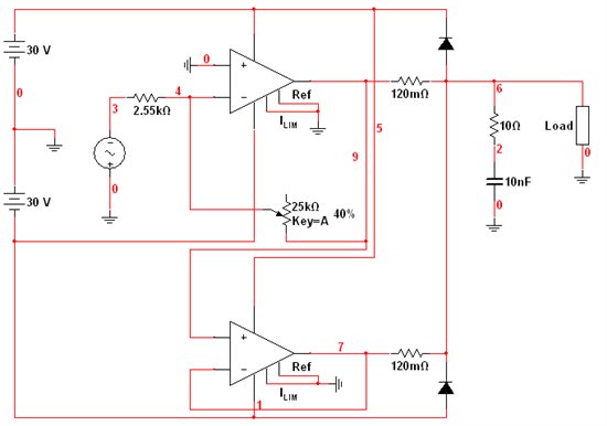
I'm a Ph.D. student currently designing a general purpose voltage source to perform frequency response analysis on various elements. I'm using two OPA549 with their outputs in parallel to increase the total output current. The global schematic of my circuit is :

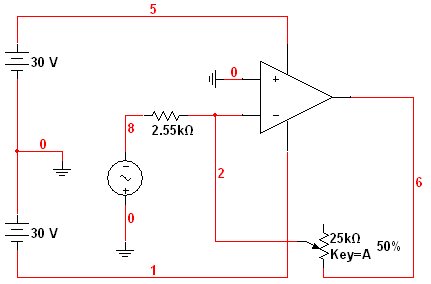
After some initial debugging, I came to test each of the Op-Amp independently. During one of these tests, I noted that the heat sinks of the Op-Amps became very hot even if their output were completely disconnected from the output stage. An example of such a test circuit was :

Here the only path to ground from the output is through the potentiometer, the 2.55k resistor and the signal source. The output current cannot be high enough to account for any significant heat of the chip, nor is the quiescent current wich is about 30 mA. The source signal used for this test was a 100kHz 10 Vpk sinusidal waveform, and after about 5 minutes of activity, the heat sinks of the Op-Amp (I use two 0.3°C/W heat sinks per Op-Amp, one at the tab and one at the front of the chip) became very hot when touched with hands. I don't think that this is a normal behaviour . A measurement of the output voltage gave the expected waveform however, consistent with theory.

Curiously , when I decrease the frequency of the signal source to 50 kHz (and below), no more excessive heat is generated and the heat sinks remain cool. This is puzzling. I would like to know what do you think is the cause of this problem, and if it has ever been encountered by anyone before. I doubt a solution can be found for it, and I'm now considering to limit the use of my circuit to 50 kHz maximum (instead of 100 kHz initially) seeing that much more heat would be generated at full load.

When I built my circuit, I soldered the wires directly on the pins of the Op-Amps using a professional 260/200 Watt soldering gun. This is a very effective tool but it generates so much heat that I think it could have damaged the chips somehow. Could it explain the problem? And if yes, seeing that my circuit works well at lower frequencies, should I still think of replacing my Op-Amps?

Thank's for your answers

  • Hi Bastien,

    Thank you for providing the circuit schematics.  Is your circuit not working because the OPA549 is heating up to the point that it goes into thermal shutdown?

    You can measure the voltage at pin 9 (which is an Enable/Status pin); in your case, with the reference pin grounded, if the voltage is at +0.8V or less, then the part is in thermal shutdown.

    With your heatsinks connected to the part, the datasheet of the OPA549 tells me that the thermal resistance will be 1.4ºC/W.  Even with multiple large heatsinks, that copper tab can only dissipate so much heat.  Still, with a thermal resistance of 1.4ºC/W, the OPA546 will only reach a temperature near it's thermal shutdown when its dissipating more than 100 Watts.

    Measure the power supply current as you increase the input signal frequency.  You may notice that the quiescent current greatly increases with frequency; this is especially true with power op-amps.  The op-amp output stage is most likely not able to switch fast enough and both the internal pull-up and pull-down networks are ON, creating a short from the positive supply rail to the negative supply rail.

    I also noticed that your 100kHz 10Vpk input signal is driving the output voltage into the rail (with your circuit gain of 5) and the op-amp is slew-rate limited, where operation is no longer linear and less defined.  You may need to decrease the frequency or amplitude of your input signal. 

    The OPA549 has a typical output voltage slew rate of 9V/μs.  You are attemping to have the op-amp slew at 17.6V/μs:
    Slew rate(V/s) = 2*π*freq*Vpeak = 2*π*100k*28V = 17.6V/μs
    where Vpeak is the output peak voltage which is VDD-2V (the maximum output voltage, 2V below the supply)

    Best Regards,
    Chris

  • Hi Christopher,

    Thank you for your response. I first tested my circuit (first diagram) at low frequencies (<10 kHz) with large resistive, inductive and capacitive loads. It worked properly with very low distortion. The thermal shut down did not activate. At around 20 kHz, I started noticing a significant distorsion which curiously appeared only in the positive half of the output waveform. This lead me to investigate the output of the Op-Amps separately when disconnected from the output stage. It proved that the outputs of the Op-Amps were very clean (at 20 kHz), and thus that there was a problem in the output stage (I suspect one of the schottky diodes to cause this, but it seems a strange problem since I believe the feedback should be able to overcome this). This was not a problem related to the Op-Amps so I didn't mention it in my original post.

    Further tests of the Op-Amps with their output disconnected from the output stage lead me to discover the problems I first mentionned.

    Christopher Hall said:
    Measure the power supply current as you increase the input signal frequency.  You may notice that the quiescent current greatly increases with frequency; this is especially true with power op-amps.  The op-amp output stage is most likely not able to switch fast enough and both the internal pull-up and pull-down networks are ON, creating a short from the positive supply rail to the negative supply rail.

    I thought about it but I did not measure the power supply current going into the Op-Amps because all of my wires were already well soldered. It was obvious however that some great amount of current was flowing from V+ to V-, causing the Op-Amps to heat. What I did not suspect however was that this behavious could be normal at high frequencies. This could mean that the Op-Amps were not damaged by the heat of my soldering gun as I thought. I will make an experiment tonight by testing a new Op-Amp at 100 kHz without soldering it and see if it heats as much.

    Christopher Hall said:
    I also noticed that your 100kHz 10Vpk input signal is driving the output voltage into the rail (with your circuit gain of 5) and the op-amp is slew-rate limited, where operation is no longer linear and less defined.  You may need to decrease the frequency or amplitude of your input signal. 

    Yes, as it is it will clip when the gain is approximately 5. I did not intend to use my circuit in such conditions but I now have increased my input source resistor from 2.55k to 5.1k. Thank you for the note regarding the slew rate. I had completely omitted any calculation regarding this. It now makes sens and also explains the distortions I witnessed in the output signal. However, you suggested to decrease the amplitude of the input signal, and I don't see how this could help reduce the distortion in the output if it remains at a given amplitude. Would you rather mean to decrease the amplitude of the output by reducing that of the input?

    A quick calculation shows that SR(f=50 kHz) = 2*pi*(50e3)*28 = 8.8 V/μs, and the second figure on the left column of page 6 of the datasheep shows that there should be no slew rate-induced distortion at 50 kHz. Still, it seems that my output waveform is somewhat highly distorted at this frequency. From page 5 of the datasheet, it seems however that the THD is likely to be >1% at 50 kHz. I'll take some screenshots of my recorded waveforms tonight to post here, but I wonder if the distortion could be solely attributable to the THD specs of the Op-Amp. I still suspect the heat of my soldering gun to have caused some damage.

  • You got the right idea to decrease the gain of the circuit such that the output doesn't clip, because even if you were to reduce the input signal frequency to 50kHz you still could be driving the op-amp into the slew rate limit if your output was clipping. 

    Example:
    Notice the two sinewaves in the image below. The dotted lines are the ouput voltage limits, and two output voltage waves of the same frequency are shown.  The larger amplitude sinwave is an output that will clip at ± 28V, however, it has an effective peak voltage at 50V even though it will be clipped at 28V.  This can be seen in the larger dV/dt slope of the 50Vpk sinewave at the zero-crossing.

    - Chris

  • Yes, absolutely, I get it. Thank's for the drawing. However, for my transfert function analysis, I intended to use only sine waves as inputs (and outputs), with obviously no clipping which I believe should introduce much more distortion that what would be seen when the output is limited by the slew rate.

    I just finished some experiments to test some of the problem discussed earlier. My test circuit was similar to that of my original post, with the 2.55k resistor replaced by a 5.1k.

    For this test I used one of the Op-Amp of my original circuit (with two Op-Amps) shown in my first post. At 50 kHz, the heat sinks remained cool and I recorded the following waveforms :

    We can see here that the output is very clean, with no distortion. After using the same circuit but just setting the gain to approximately 2, I recorded :

    Here the output is lagging the input a little bit more, which is not so important, but it is a lot more distorted. It could appear neglectable at first sight but it does matter when it comes to precise phase calculations. At this point I still thought that this problem was due to overheating the Op-Amp when soldering. To verify this, I built a small circuit similar to the previous one with a new OPA549 and a 20k resistor instead of the 25k potentiometer. I recorded waveforms literally identical to the last ones. There was the same distortion. Moreover, having no heat sink, I noticed that the tab quickly got very hot, which confirms that the behaviour observed with my initial Op-Amps at 100 kHz was normal, but yet unwanted.

    From this experiment I concluded that I had not damaged the initial Op-Amps when soldering. However, I am still questioning myself as to why the output voltage distorts in such a way at 50 kHz when the gain is increased. The slew rate is about 2*pi*50e3*20 ~= 6.3 V/us and should not be a problem according to the datasheet. Besides the slew rate, I see no other factor or parameter that could induce distortion when the output voltage (or gain) is increased at a given frequency.

    I am now quite satisfied with all of these investigations so far. I will now use the Op-Amps within their acceptable limits.

  • Bastien,

    I think you are still seeing some slew rate limiting, even at 6.3V/us.  I did a Tina-TI simulation with the OPA549 model and was able to replicate the results.  Some of the distortion you're seeing is due to non-symetrical slew rate limiting.  The positive and negative slew rates are slightly different, so your output waveform see's additional frequency content.

    It could be that your op-amp has a little lower maximum slew rate due to process variations, however, I found it interesting that the OPA549 Tina model was slewing under similar conditions.  I would operate you circuit at a lower gain, or lower frequency to avoid these distortions.  If you need higher gain at 50kHz you might consider an op-amp with a higher gain-bandwidth product.

    I attached my Tina-TI simultation file so you could look at it and modify it if you like.

    Best regards,
    Chris

    OPA549 50kHz input.TSC
  • Hi Christopher,

    Thank you for this simulation. I did not know about the TINA simulator. I have downloaded it and tested your circuit. It is almost identical to what I measure with my scope. It seems however that I measure a little bit less distortion in my circuit.

    My goal would be to generate a 20 Vpk sine wave at 50 kHz with no distortion (or almost). I find it strange because from the maximum output voltage swing graph of the datasheet, I should see no slew rate distortion at 50 kHz for a 26 Vpk output. And from the slew rate graph, it seems like I would need to operate the Op-Amp below -50 °C to be limited to 6.5 V/us. If this distortion is really caused by the slew rate, then we can only conclude that the Op-Amps do not meet the specs. Testing the same circuit with another new OPA549 also gave the same distortion.

    Anyway, I had a new idea today to minimize or eliminate this distortion. If there is no distortion when G=1, maybe I could pre-amp the input signal at the proper level with a low-power low-distortion Op-Amp and then use my two OPA549 as followers. I tested this with TINA-TI and it didn't work, but I'll give it a try tomorrow for curiosity.


  • Just a hint:

    Slewrate is measured with a large voltage step (50Vpp @ G=1), not a sinus wave. The slewrate of the input signal for the measurement has a much higher slewrate than the amplifier, hence the input is overdriven to as much as 50V (V+ minus V-) right from the start. You cannot achieve this by applying a 50kHz sinus.

    In other words: for the datasheet value, the amp does its best to charge its internal miller capacitor with the maximum current provided by some internal current source, and this gives a straight slope, not a sinus. The amp is struggling to reach the peak output voltage as fast as possible, but there is no means to control the waveform anymore, for it is completely determined by the charging function of the miller capacitor.

    The datasheet still states you should get an undistorted output of 27Vp at nearly 60kHz. I'm suspecting that noone has ever tested this, and the diagram shown on page 6 of the datasheet was just calculated from the slewrate that has been determined by the method descrived above. This will of course not work like intended, since the driving conditions are so different. The SPICE model is based on true component values and usually gives very accurate results for simple questions like frequency response or slewrate. So if the simulation confirms what the practical testing has proven (or gives even worse results, indicating that theSPICE model is based on w.c. considerations) we can safely assume that the datasheet is not quite correct regarding this particular diagram.

    Furthermore, the slewrate was determined at unity gain, i.e. in the noninverting circuit. With a comon mode voltage step of 50Vpp, the amplifier might behave slightly different than it does in the inverting circuit, where no common mode voltage applies.

    Finally you should consider the small signal bandwidth also, for it is rather low with just 900kHz for unity gain. With a noise gain of 5 (20k/5k) or even more, the 3dB bandwidth of the amplifier drops to 180kHz or even lower. This gives a loop gain (the difference of open to closed loop gain) of less than 4 at 50kHz. With that small amount of feedback, one cannot expect an undistorted output at full output swing anymore.

    Now after analying all the causes, what can be done to solve the problem? I would recommend a high voltage preamplifier, such as the OPA 551, in order to amplify the generator signal to the desired level and use the OPA 549 as a non-inverting unity gain buffer.  The 551 provides 3MHz GBW and 15V/µs SR, whixh should be a considerable improvement over the OPA 549 alone. Alternatively, an even faster preamplifier operating from +/-15V supply lines could be used, when the OPA549 is set to a gain of 2. With the Spice Simulation, either option can be investigated in advance and the more satisfying can be implemented.

    Regards, Herbert

  • Hi Herbert,

    Thank's for these very useful precisions. I can now understand why I still saw distortions at 50 kHz. Overdriving the input enables the Op-Amp to achieve a higher slew rate than what is normally achieved under a zero differential voltage. Your last suggestion was exactly what I wanted to do yesterday, but couldn't have time to do it. At 50 kHz and an input signal of Vp = 5 V, I see no distortion when G = 2. So a +/- 15V Op-Amp could be fine. However, simulating the OPA549 as a follower with a 20 Vp signal input (at 50 kHz) with TINA-TI gives a distorted output. So according to this result, using the OPA549 as a unity gain buffer shouldn't bring any improvement. However, I'm still curious to see what should happen in practice.