This thread has been locked.

If you have a related question, please click the "Ask a related question" button in the top right corner. The newly created question will be automatically linked to this question.

OPA350: opa350

Part Number: OPA350

Dear everyone,

I made a Photodiode Transimpedance Amplifier as the picture.

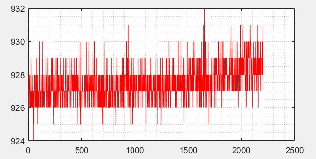
I did not know why the voltage drift happened, although the light intensity was stable.

In this circuit, I used a feedback resistor which is a series of many smaller resistors. 

How can I circumvent this problem, please?

I would like to use that amplifier to monitor any tiny change in light intensity. The photodiode is put into a small box with a very small hole on it.

Thanks a lot  

  • Hi Son,

    To assist you we need more information about your application. What is the total feedback resistance? What is your supply voltage? What kind of current levels are you working with? What is the issue you are seeing, do you have oscilloscope plots that demonstrate the behavior? The more information you share, the better we can assist you. Typically, you need to include a feedback capacitor to compensate for the interaction between the photodiode capacitance and the large feedback resistance. Without this capacitor, it is very likely that your op amp is unstable.  Also, please be aware that since OPA350 output can only swing linearly within 50mV above its negative rail, under the dark current condition (no current in diode) for the circuit to work properly, you may NOT power the circuit from a single supply.  Btw, check the polarity of the Isignal - the way it's shown would result in the output to go negative and thus require OPA350 to operate from a negative supply voltage.

  • Dear Zak,

    The feedback is 500MOhm. The supply voltage is a single 5V. The current is about 10^-8A=10nA. The photodiode I used is BPW 34. 

    I also used a feedback10pF cap. 

    One of the plots I got from the light-monitor data. It can be seen the line goes up slightly.

    With the power supply, did you mean I must apply bias mode for the diode?

    Thank you very much for your reply.

  • Hi Son,

    Thank you for providing this information. I have simulated your circuit (see attached) and confirmed your configuration is stable. Is the y-axis in your attached plot supposed to be output voltage in mV? From the simulation, your RMS noise on the output is going to be about 2mVrms, which means you could expect to see roughly 12mVpp in noise on your output. With the amount of data provided it's hard to say if the output is actually drifting, but it looks like it has shifted by 1.5mV. Given the gain you are operating in, any number of things could be influencing the measurement. With the 500MOhm resistance this would translate to a shift of roughly 3pA in the photodiode. With the sensitivity of your chosen photodiode, this would correspond to an incredibly minute change in irradiance (the photodiode curves don't extend low enough to say exactly how much), so I would question if something in the setup shifted slightly to skew the measurement (light positioning relative to photodiode, intensity of ambient light entering the box, etc.)

    What kind of load are you driving with this? Additionally, it could be that the bias current or offset voltage are moving slightly with temperature because with the large gain even a slight shift in temperature could produce this amount of offset. Was this data taken after the op amp had been running for a while or immediately after startup? I think it will be very difficult to isolate the source of this error, but you may try removing the photodiode and connecting a constant current source to see if you can replicate the behavior. This will tell you if it is related to a change in the photodiode/light or a shift in the op amp parameters.

    Regarding the power supply, the output of the OPA350 cannot swing all the way to ground, so whenever there is no light shining on the photodiode, you would want to have some bias applied to the noninverting pin of the op amp to keep the output from saturating. Given that the dark current of your chosen photodiode is in the nanoamp range though, I don't think this should be an issue for you.

    OPA350 TIA.TSC

  • Hi Zak,

    The load driven with this is a stepper motor which I think it can affect the output. They share a 5V source.

    As you said, the bias current of the opamp also could be the main agent that I will test it by a current source.

    To the shift, when I connect the circuit to the whole device, it can be seen right the way. Actually, the observed curved will go down gradually before a little bit swinging around a certain horizontal line.

    Thank you very much for your reply.