Part Number: OPA1632
Other Parts Discussed in Thread: PCM4202, PCM4222, OPA1652, TINA-TI
-
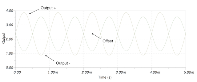
I am using the OPA1632 as an audio ADC (PCM4202) input driver, using the circuit shown in Figure 13 of the ADC data sheet, and also shown in Figure 14 of the OPA1632 data sheet. The input to the driver circuit is single ended, so the Vin- is grounded (before the 1k resistor). Simulating with both TI-TINA and LTSpice give me the same odd result -- the outputs of the circuit are asymmetric, and they are offset from the offset. See the attached image.
The input to the circuit is a 1 kHz 10Vp (20 v p-p) sine wave. The obvious question -- is this a simulation artifact, or is this really how the circuit operates?

- PCM4202 data sheet shows the OPA1632 VOCM input being driven by the ADC's VCOM out buffered by an op-amp through a 1k series resistor. PCM4222 data sheet shows the OPA1632 VCOM input driven by the op-amp directly (no series resistor). The OPA1632's data sheet, figure 14, shows the op-amp directly driving the VOCM pin with no series resistor. What is the intent of the series resistor? In the image above, it is modeled with a 2.5 V voltage source buffered by an OPA1652 as a follower. I noticed that if I include it in the simulation, the voltage at the VOCM pin drops from 2.5 V to 2.34 V. See the following image. This doesn't make sense -- what is going on here?