This thread has been locked.

If you have a related question, please click the "Ask a related question" button in the top right corner. The newly created question will be automatically linked to this question.

INA219: Question about I2C Data Hold Time

Guru 19585 points
Part Number: INA219

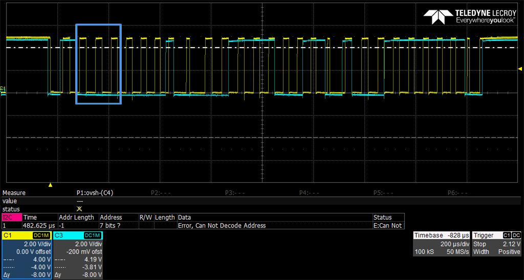
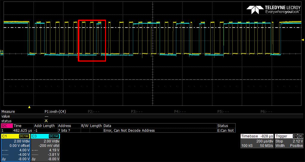
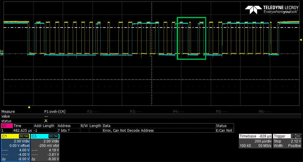
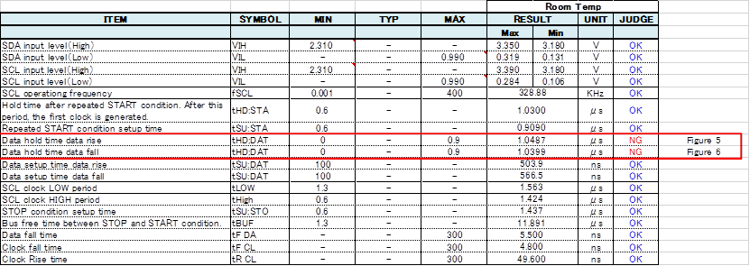
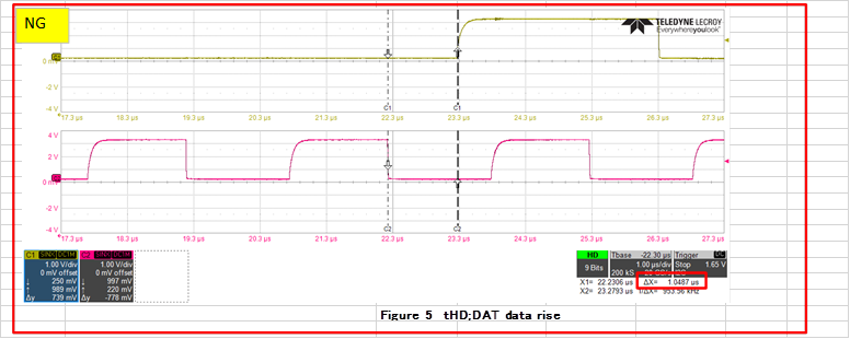
On the customer evaluating INA219B, I2C Data hold time is over the definition range.

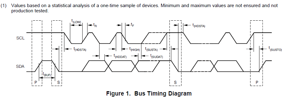
⇒Required 900ns_max at Fast Mode (Datasheet page-6), but below test results are near 1000ns. 

I think that test results should keep definition range, but tHD spec is depend on fSCL spec.

(Foe example; If in the case of fSCK:340kHz, tHD range will be ease)

Is it correct? If correct, please let me know about the relation for fSCL and tHD spec.

Best regards,

Satoshi

  • Satoshi,

    I hope to solve this issue and want to make sure I understand you.

    In the oscilloscope pictures you provided, is the INA219 being driven by a master controller (thus in transmitting data) or is the INA219 reading data? Are you experiencing problems with your system?

    Also, are you saying that when the f_SCK = 340kHz, you are seeing the data hold time (tHD) under 900ns?

    Peter Iliya
    Current Shunt Monitors Applications
  • Peter-san

    Thank you for reply,
    I answer your question, please see below;

    ・Waveform picture is the INA219 data(Write mode).
    ・Customer can't check problem because timing is start to prototype stage.

    Best regards,
    Satoshi
  • Satoshi-san


    If the INA219 is writing data to the master and its data hold time is ~1000ns, then this is technically out of the specified maximum range, but this should realistically NOT affect data transmission and these specs are not guaranteed as mentioned in the datasheet, note 1 below. So a maximum specification here is not a 6-sigma bound that we provide with our electrical characteristic specifications.


    I will try to find more information for you on the characterization of this timing.


    Peter Iliya

    Current Sensing Applications

  • Peter-san

    Thank you for advice.

    For addition, please let me know about max value of tHDDAT specification below.
    ①What is the background of described tHDDAT_max? (Fast mode: 900ns)
    ②If exceed tHDDAT_max (ex. 1000ns), is there possibility of abnormal operation?
    ③Is tHDDAT_max spec depend on operating frequency? (for example, 400kHz⇒900ns, 300kHz⇒1000ns, etc)
     Or, is tHDDAT constant regardless of SCL frequency?

    Best regards,
    Satoshi
  • Satoshi-san

    How many devices are on this I2C bus line? What are the pull-up resistor values? What are the specs for your master I2C part?

    1. The tHDDAT spec actually has two parts that have been combined into our datasheet. First part: the max 900ns spec is the tHHDAT Output (or delay) time of our INA219 outputting or writing data once it receives a falling SCL edge. The second part is the minimum 0ns which is the tHHDAT Input time that is required of the master. This means that the master could drive the INA219 with 0a ns tHHDAT at a minimum.

    2. I need more information from the questions I asked above to answer this better.

    3. The tHHDAT should not be dependent on frequency of SCL.

    Sincerely,
    Peter Iliya
    Current Shunt Monitors Applications
  • Dear Satoshi-san,


    According to our INA219 test data there were no units that ever got close to 900ns tHHDAT. Also, tests I have just run with the INA219 EVM have not yielded any tHHDAT greater than 270ns even with the SCL frequency at around ~15kHz, so there is definitely no dependence of the tHHDAT with SCL frequency. The tHHDAT really is related to the INA219’s physical delay in responding to clock signals and this does not change with SCL frequency.


    Where exactly in the I2C packet is your oscilloscope shot occurring? Even if it happening when the INA219 is reading back data there are 3 possibilities that line up with your zoomed-in oscilloscope shot. In each possibility (colored boxes), the tHHDAT could be much longer than 900ns because it is not being driven by the INA219, but actually the microcontroller.


    1.Blue Box: You are zoomed in on the master (microcontroller) writing a ‘001’ as part of the INA219’s I2C address when it is specifying which INA219 address it wants data from. See INA219EVM waveform below. Note that in this case the INA219 address is 1000000, but if your INA219’s slave address is set to 1001000, then this could be the case.


    2.Red Box: You are zoomed in on the master writing its read bit (‘1’) just before the INA219 acknowledges and then begins reading back its data over the SDA line.


    3.Green Box: You are zoomed in on D7 and the extended hold time is due to the fact that the master still has control over the SDA line during and a little after it acknowledges the previous MSByte from the INA219.


    An overall oscilloscope screen shot of the I2C communication would be beneficial to further analysis of your problem.


    Thanks,

    Peter Iliya

    Current Sense Amplifiers Applications


  • Satoshi-san,

    Has your issue been solved? I assume you need no further assistance, but please post to the forum if you have more questions.

    Thanks,
    Peter Iliya
    Current Sense Applications
  • Peter-san

    Sorry for reply delay.
    This question was cleared, thank you.

    Best regards,
    Satoshi