This thread has been locked.

If you have a related question, please click the "Ask a related question" button in the top right corner. The newly created question will be automatically linked to this question.

THS4503EVM: Differential output Power different from single ended output power

Part Number: THS4503EVM
Other Parts Discussed in Thread: THS4503

Hi

I wanted to achieve a gain of 10 by changing the feed back resistors to 1.3K and 118 Ohms as suggested. The input voltage maximum is 1V peak to peak  @ 100MHz. I have done multiple test cases.

Case 1: Original EVM

I have tested to THS4503EVM, by giving a single ended input of voltage of 1Vpeak to peak @ 100MHz (using 50Ohm cable) as suggested in the user guide. The output voltage @ Vout+ and Vout- is equal to 520mV peak to peak wheareas at the single ended output after the transformer is 90mV peak to peak. Since the gain is 1, we must get the same or similar output  @ Vout+ and Vout- .

Case 2: Removed the input termination resistor (RT = 50Ohms) on the Vin- input (Since the source impedance is already 50Ohms).  The output voltage @ Vout+ and Vout- is equal to 1V peak to peak and at the single ended output after the transformer is 170mV peak to peak. I see we here we get 1V peak to peak output on Vout+ and Vout-. However, I am unsure why am not getting double the output power at the single ended output, i.e., at Vout after the transformer. 

The output differential load resistance is set to 800Ohms using the transformer (1:4) transformer, is this load reducing output gain (attenuating instead of gain).

What is the best way to achieve a 50Ohm impedance at the output of Vout, and double the voltage swing.

Thanks

Venu

  • Hi,

    If you are using the default configuration of the EVM then you should expect 16.7 dB of attenuation between the outputs of the amplifier and the output voltage measured at the transformer. The output resistor divider causes an attenuation of approximately 0.3 V/V and then the transformer further reduces the voltage by 2:1 voltage ratio. The transformer is a 4:1 Ohms ratio.

    Also, it is important to include the resistor R11 if you are using a high impedance measurement such as an oscilloscope set to 1 MOhm impedance mode. Otherwise it R11 should not be included and you should connect to 50 Ohm measurement equipment.

    You also need to keep the R1 termination resistor on the inverting input because it provides the 50 Ohm match to the signal source, which reduces changes of reflections due to cable lengths. The default gain is also set to account for the termination resistor and will have a slight differential output offset and gain error without it.

    For your first measurement with 1Vpp input, were you measuring 520mVpp at each output of differentially between the outputs? I would expect the device to be in a gain close to 1 V/V in the default configuration, so you should see 1 Vpp differentially at the output.

    Regards,
  • Ok, I understood this part. The output resistor divider causes an attenuation of approximately 0.3 V/V and then the transformer further reduces the voltage by 2:1 voltage ratio using the transformer.

    What are the values of resistors to get a 10V/V differential gain using split power supply +/-5V. I tried using TINA to find the best values, unfortunately for 1Vpp input i can get a max output of 3Vpp using 1.3K feedback resistor and 118 Ohm Rg resistor and Rt=64.9, but the document suggests a gain of10V/V. What am i doing wrong ?

    I am using a 50Ohm measurement equipment, so I am not connecting R11.  For the input side i was measuring the 520mVpp at each output. That means I should measure 1Vpp differentially. How do I get 1Vpp at the output of the transformer and still match it 50Ohms ?

  • Hi,

    Are you only seeing a 3Vpp output signal in your TINA simulation? If you attach the simulation here, I can take a look at it to see if there are any issues.

    To get 1Vpp at the output of the transformer you will need to either use more gain on the amplifier, or use a different load network and transformer. However, if you directly load the output with 50 Ohms, it may affect the amplifier performance. Typically we only use 50 Ohm matching circuits to make interfacing with test equipment easier and would load the amplifier differently for its final application.

    Regards,

  • Hi Jacob

    Here are the snapshots, I am using the same reference TI has provided and changed it accordingly. The Feedback resistor is 1.3k amd Rg is 118Ohms with Rt 56.2 Ohms.  I am checking different outputs VM1 is the output of transformer (1:4) transformer (N^2 turns), VM3 is the differential output across the 800Ohms resistor. This is measured @ 100MHz sine wave frequency.

    The results are shown below, VM3 is 3Vpp.

    I have a single ended mixer following this amplifier instead of a differential component with IF freq-100MHz. That is the reason i am trying to convert to single ended 50Ohms impedance.

    Thanks

    Venu

  • Hi Venu,

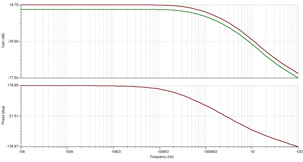
    Your simulation is correct. The issue is that you are trying to use a 100 MHz signal in the device at a gain of 10 V/V. The gain bandwidth of the THS4503 is only 300 MHz, which means that the -3dB bandwidth at a gain of 10 V/V will be 30 MHz. You can see this if you look at the AC response in your TINA simulation, which should look like the one below. At 100 MHz the gain is at about 10 dB (~3 V/V), which makes sense with your transient simulation. If you need 100 MHz for your signal at a gain of 10, you will need to use an amplifier with at least 1 GHz of GBW.  

    Regards,