


Part Number: ADS4129
Other Parts Discussed in Thread: THS4303, THS4541, LMH6554
Hi,
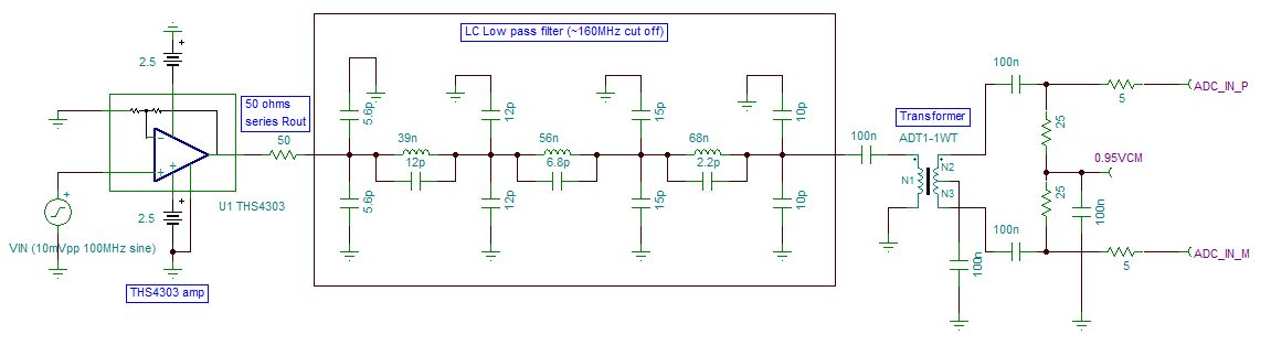
Please find attached a snapshot of the ADC input drive circuitry I'm planning to use for for the ADS4129 ADC operating at 250MSPS Fs. In my application, my input signal is a 10mVpp 100MHz sine wave, which will be gained up by 10X by the fixed gain amp THS4303 as shown in the diagram. A 50 ohm resistance will be present at the THS4303 output after which there will be ~160MHz cut off LC low pass filter in order to reduce the in band noise for the ADC (I'm planning to provide an option to bypass this LPF too).
After this comes a 1:1 ADT1-1WT transformer which does the single ended to differential conversion for the amp output signal and goes on to drive the ADC inputs as shown in the diagram. For my application, the requirement is to be able to measure the peak to peak amplitude of the incoming sine wave with at least 10% accuracy. Can you please confirm if you see any issues with the proposed drive circuitry below?
Thanks,
Anoop


